
Part of the Doosan Repair Manuals.
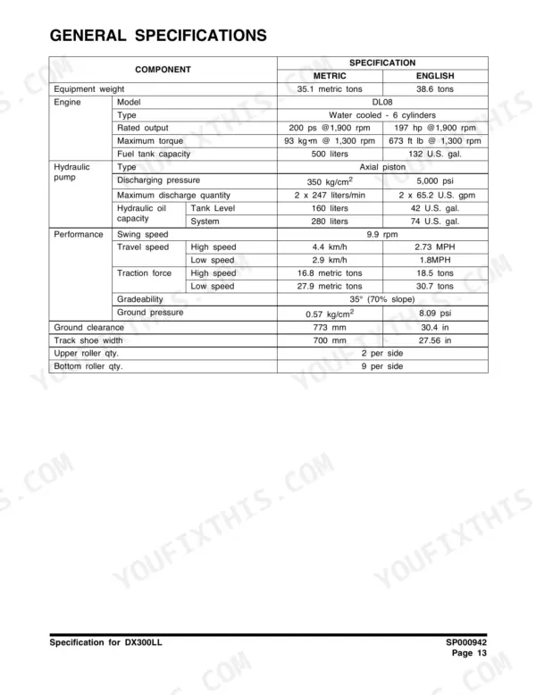
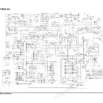
Looking for a Doosan DX300LL shop manual PDF with real factory data? This 806-page shop manual (OEM #K1011789E) walks you through the DX300LL track excavator from the swing bearing down to the track links. Inside: full hydraulic schematics, electrical schematics for chasing wiring faults, a dedicated hydraulic troubleshooting and testing section, and page after page of teardown procedures for the main control valve, swing motor, travel motor, and axial piston pump. You also get standard torque tables plus rebuild steps for cylinders, the center joint, and the boom and stick. Fill the fuel tank to 500 liters and check track link pitch at 203.2 mm before you send it back to work. No more chasing hydraulic pressure faults with guesswork. Bookmarked with a full text layer; jump straight to a section or search any spec from the phone in your shop.
What's Inside This Doosan DX300LL Manual
| System | Pages | Key Topics |
|---|---|---|
| Safety | 5-50 | |
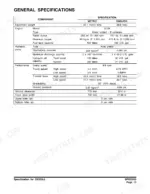
| Specifications | 51-76 | Specification for DX300LL |
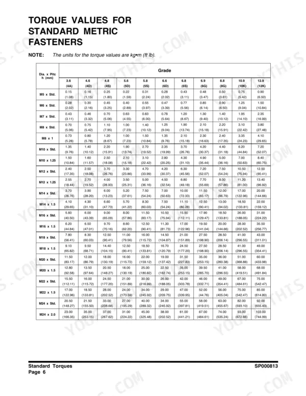
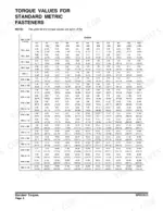
| General Maintenance | 77-114 | General Maintenance Procedures, Standard Torques |
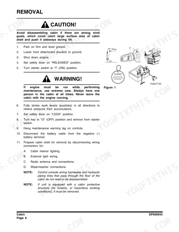
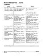
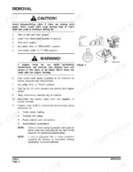
| Upper Structure | 115-220 | Cabin, Counterweight, Fuel Tank, Fuel Transfer Pump, Swing Bearing, Swing Reduction Gear |
| Lower Structure and Chassis | 221-250 | Track Assembly |
| Engine and Drive Train | 251-260 | Drive Coupling (Main Pump) |
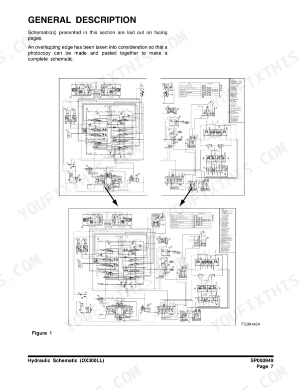
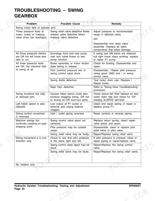
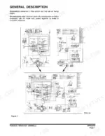
| Hydraulic System Troubleshooting, Testing and Adjustment | 263-300 | Safety Precautions, Applicable Models, Hydraulic System - General Notes, Hydraulic Schematic, Operation of Working Components, Boom Operating Circuit |
| Accumulator | 301-348 | Safety Precautions, Applicable Models, General Description |
| Swing Motor | 349-388 | Safety Precautions, Applicable Models, General Description, Theory of Operation, Makeup Check Valve, Operation of Time Delay Valve |
| Travel Motor SP000253 | 389-448 | Safety Precautions, Applicable Models, General Description, Theory of Operation, Special Tools and Materials, Hydraulic Motor Part |
| Main Control Valve | 449-514 | Safety Precautions, Applicable Models, General Description, Theory of Operation, Troubleshooting, Testing and Adjustment |
| Axial Piston Pump | 515-558 | Safety Precautions, Applicable Models, General Description, Model Number Designation, Theory of Operation |
| Remote Control Valve (Work Lever / Joystick) | 559-606 | Safety Precautions, Applicable Models, General Description, Theory of Operation, Torques, Tools and Materials |
| Solenoid Valve Assembly | 607-630 | Safety Precautions, Applicable Models, Package, Functions of Solenoid Valve Assembly Package, Assembly Diagram and Tools Required, Solenoid Valve Diagram |
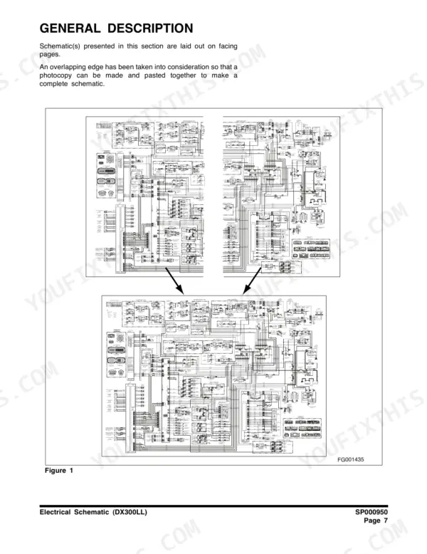
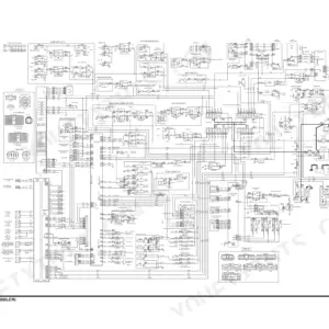
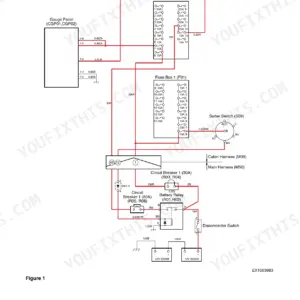
| Electrical System | 631-768 | Air Conditioner SP000025, Electrical Schematic (DX300LL) |
| Attachments | 769-806 | Boom and Stick, Boom and Arm (Exca. Front Option), Bucket (Exca. Front Option) |
Quick Reference Specifications
| Specification | Value | Page |
|---|---|---|
| Worm Drive - Under 44 mm (1-3/4 in) Open Diameter | 0.2 - 0.3 kg•m (20 - 30 in lb) | p. 108 |
| Worm Drive - Over 44 mm (1-3/4 in) Open Diameter | 0.5 - 0.6 kg•m (40 - 50 in lb) | p. 108 |
| Fuel tank capacity | 500 liters (132 U.S. gal) | p. 145 |
| Link Pitch | 203.2 mm | p. 233 |
| Bushing Outside Diameter | 66.5 mm | p. 233 |
| Interference between bushing and link | 0.35 - 0.464 mm | p. 233 |
| Interference between regular pin and link | 0.273 - 0.485 mm | p. 233 |
| Main relief high-stage pressure | 350 bar (5075 psi) | p. 283 |
| Low-stage main relief pressure | 330 bar to 335 bar (4,785 psi to 4,858 psi) | p. 283 |
| Clearance between the spindle and thrust plate | 0.5 mm | p. 317 |
| Clearance between the spindle and body of the center swivel | 0.1 mm | p. 317 |
| Coil resistance | 26.7Ω @ 20°C | p. 618 |
Doosan DX300LL Common Problems This Manual Covers
Doosan DX300LL hydraulic functions slow and weak, main pump making abnormal grinding noise
Check hydraulic oil level first; the system holds 280 liters, and a low reservoir pulls air into the suction line. Bleed the circuit, then test main relief pressure against the 330 kg/cm2 normal setting on page 70. If pressure stays low with pump whine, follow the troubleshooting procedures and inspect case drain oil for metal.
Manual Section: Hydraulic System Troubleshooting, Testing and AdjustmentOne track drags or travel gets jerky, grinding noise from final drive
Drain and inspect the travel motor gearbox oil for metal flake, then refill with 5.5 liters of gear oil per page 407. Check track tension before condemning the motor; a loose chain mimics jerky travel. Test travel motor rotation and brake release with the tracks jacked clear of the ground.
Manual Section: Travel Motor Troubleshooting p. 407Swing feels sluggish, drifts on slopes, or upper structure shudders during rotation
Test swing relief valve pressure with both swing locks engaged; you want 270 to 280 bar, checked per the procedure on page 291. Low readings point to a worn relief valve or internal swing motor leakage. Also verify swing speed reaches the rated 9.9 rpm before tearing into the gearbox.
Manual Section: Swing Motor Troubleshooting p. 291Track tension keeps dropping between adjustments, link pins and bushings wearing out fast
Measure link pitch; new spec is 203.2 mm per page 233, and stretch beyond the service limit means pin and bushing turn or replacement. Check bushing outside diameter against the 66.5 mm new dimension while you are under there. Adjust tension with the grease cylinder and clean packed mud from the track frame daily.
Manual Section: Lower Structure and Chassis p. 233Intermittent electrical faults, slow cranking, and fault codes flickering on the display
Clean and tighten both battery terminals and the chassis ground strap before chasing codes; most phantom faults are poor grounds. Trace suspect circuits with the wiring diagram. If one hydraulic function drops out, measure the solenoid coil resistance, which should read 26.7Ω at 20°C per page 618.
Manual Section: Electrical System Troubleshooting (e-EPOS) p. 618Hydraulic oil leaking at center joint and weeping around valve housing ports
Replace the center joint O-rings and check spindle wear before reassembly; clearance between spindle and body should not exceed 0.1 mm, with 0.5 mm at the thrust plate, per page 317. On the valve housing, retorque the mounting nuts evenly to 21 kg•m so the housing does not skew.
Manual Section: Hydraulics p. 317Frequently Asked Questions
How do I reset the service interval for filters and oils on a Doosan DX300LL?
To reset the operating hours for filters and oils, navigate to the 'Filter / Oil Info' mode in the main menu. After changing the filter and oil, use the reset function to clear the operating hours until the next service interval. This is detailed on page 705. p. 705
What is the procedure to reset the service interval for the fuel filter?
Navigate to the 'FILTER / OIL INFO' screen on the monitor. Select '1. Fuel Filter' and use the reset button to clear the current hours (0025) to begin a new service interval. p. 705
What is the tightening torque for the main relief valve on the DX300LL?
The tightening torque for the main relief valve is 7.95 - 8.97 kg•m (58 - 65 ft lb). p. 511
What is the capacity of the fuel tank for the DX300LL?
The fuel tank capacity for the DX300LL is 500 liters (132 U.S. gal). p. 145
What is the required torque for the counterweight mounting bolts on the DX300LL?
The counterweight mounting bolts must be tightened to 250 kg•m (1,807 ft lb). p. 138
Is this Doosan DX300LL manual a download or a disc?
Immediate download of the complete 806-page searchable Shop Manual. Access it on any device, from a laptop at your desk to a phone in the field.
Is this Doosan DX300LL manual print-friendly?
Yes. Print a single page or a chapter for your own shop use, on letter or A4.







Reviews
There are no reviews yet.