

Part of the Doosan Repair Manuals.
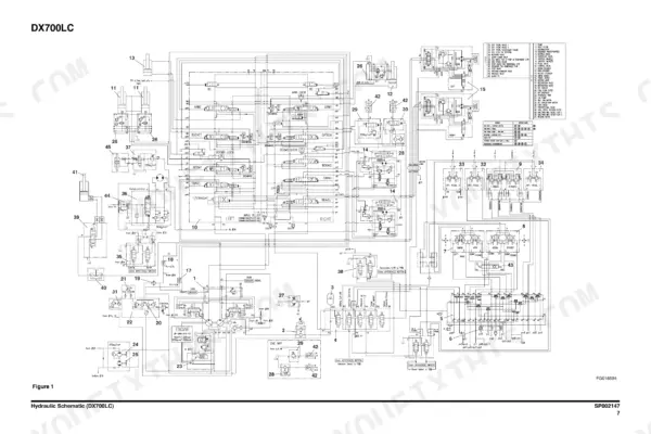
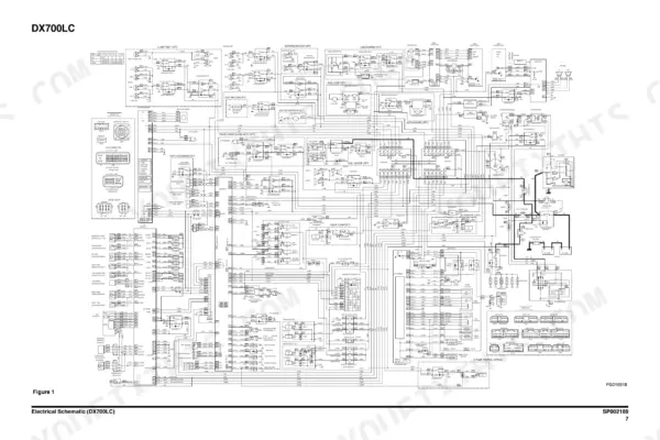
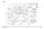
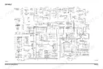
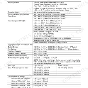
This is the factory shop manual for the 2010 Doosan DX700LC, the 70 tonne flagship of the line, publication 950106-00013E. It covers the Isuzu 6WG1-TC engine, the full hydraulic circuit from main pump and regulator through the main control valve, swing motor, travel motors and reduction gears, plus cabin and counterweight removal, track assembly wear limits, and boom and arm pin work. You get the complete hydraulic schematic (SP002147, page 997), the complete electrical schematic (SP002189, page 1125), and the machine side failure code list on page 1046. Torque tables, pressure settings, disassembly drawings and testing procedures are all here. If you keep one of these big diggers earning, this is the book the dealer techs work from.
What's Inside This Doosan DX700LC Manual
| System | Pages | Key Topics |
|---|---|---|
| Safety | 7-50 | Track Excavator Safety, Safety Precautions, To the Operator of a DOOSAN Excavator, Learn the Signal Words Used with the Safety Alert Symbol, General Safety Essentials, Accessory Applications |
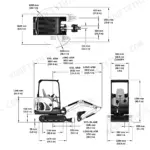
| Specifications | 51-78 | Specification for DX700LC, Safety Precautions, General Description, Component Locations, General Dimensions, Working Range |
| General Maintenance | 79-116 | General Maintenance Procedures, Safety Precautions, Welding Precautions and Guidelines, Hydraulic System - General Precautions, Maintenance Service and Repair Procedure, General Precautions |
| Upper Structure | 117-226 | Cabin, Safety Precautions, Removal, Installation, Counterweight, Warning for Counterweight and Front Attachment Removal |
| Lower Structure and Chassis | 227-272 | Track Assembly, Safety Precautions, General Description, Track Tension, Cleaning and Inspection (Wear Limits and Tolerances), Track Shoe |
| Engine and Drive Train | 273-524 | Engine, Safety Precautions, General Information, Service Precautions, Reading the Model, Engine Mechanical |
| Hydraulics - Hydraulic System Troubleshooting, Testing and Adjustment | 525-560 | Hydraulic System Troubleshooting, Testing and Adjustment, Safety Precautions, Hydraulic System - General Notes, Hydraulic Schematic, General Notes, Operation of Working Components |
| Hydraulics - Accumulator and Center Joint (Swivel) | 561-582 | Accumulator, Safety Precautions, General Description, Specifications, Center Joint (Swivel), Center Joint Disassembly Diagram |
| Hydraulics - Cylinders | 583-626 | Cylinders, Safety Precautions, Specification and Assembly Drawing, Arm Cylinder, Boom Cylinder, Function |
| Hydraulics - Swing Motor | 627-654 | Swing Motor, Safety Precautions, Instruction Manual, Indication of Type, Specifications, Construction and Working Principle |
| Hydraulics - Travel Motor | 655-704 | Travel Motor, Safety Precautions, Instruction Manual, Introuduction, Outline, Indication of Type |
| Hydraulics - Travel Reduction Gear | 705-750 | Travel Reduction Gear, Safety Precautions, General Informations, Safety Informations, Lifting and Handling, Storage |
| Hydraulics - Main Pump | 751-774 | Main Pump, Safety Precautions, Axial Piston Pump, General Description, Special Tools and Materials, Troubleshooting, Testing and Adjustment |
| Hydraulics - Regulator of Main Pump | 775-796 | Regulator of Main Pump, Safety Precautions, Naming Convention, Specifications, Overview, Operation Description |
| Hydraulics - Gear Pump for Pilot | 797-814 | Gear Pump for Pilot, Safety Precautions, Single Gear Pump, Disassembly, Reassembly, Double Gear Pump |
| Hydraulics - Main Control Valve | 815-868 | Main Control Valve, Safety Precautions, General Description, When All Spools Are in Neutral, Single Operation, Combined Operation |
| Hydraulics - Remote Control Valve (Work Lever / Joystick) | 869-898 | Remote Control Valve (Work Lever / Joystick), Safety Precautions, Safety Caution, Notes on the Operation Manual, Immunity From Responsibility, Overview |
| Hydraulics - Travel Control Valve (with Damper) | 899-924 | Travel Control Valve (with Damper), Safety Precautions, General Description, Theory of Operation, Pressure Reducing Valve, Operating Theory of Damper Mechanism |
| Hydraulics - Fan Motor (Fan Cooling Drive) and Fan Pump (Fan Cooling Drive) | 925-960 | Fan Motor (Fan Cooling Drive), Safety Precautions, Disassembling Fan Motor, Reassembling Fan Motor, Fan Pump (Fan Cooling Drive), Disassembling Fan Pump |
| Hydraulics - Solenoid Valve Assembly to Hydraulic Schematic (DX700LC) | 961-998 | Solenoid Valve Assembly, Safety Precautions, 5-Solenoid Valve, Parts List, Functions of 5-Solenoid Valve Assembly, Assembly Diagram and Tools Required |
| Electrical System | 999-1126 | Safety Precautions, Electrical Supply System, Engine Starting Circuit, Start Operation, After Start |
| Attachments | 1127-1190 | Boom and Arm, Safety Precautions, Front Attachment Pin Specifications, Front Attachment - Removal and Installation, Arm Removal Procedure, Boom Removal Procedure |
Quick Reference Specifications
| Specification | Value | Page |
|---|---|---|
| Engine model | Isuzu 6WG1-TC (AH-6WG1XYSC-01), water cooled inline 6-cylinder 24-valve OHC diesel | p. 69 |
| Rated power | 469 ps (462 hp) @ 1,800 rpm | p. 69 |
| Maximum torque | 202 kg·m (1,462 ft lb) @ 1,500 rpm | p. 69 |
| Fuel consumption at rated power | 157.4 g/ps·h (214 g/kWh) | p. 69 |
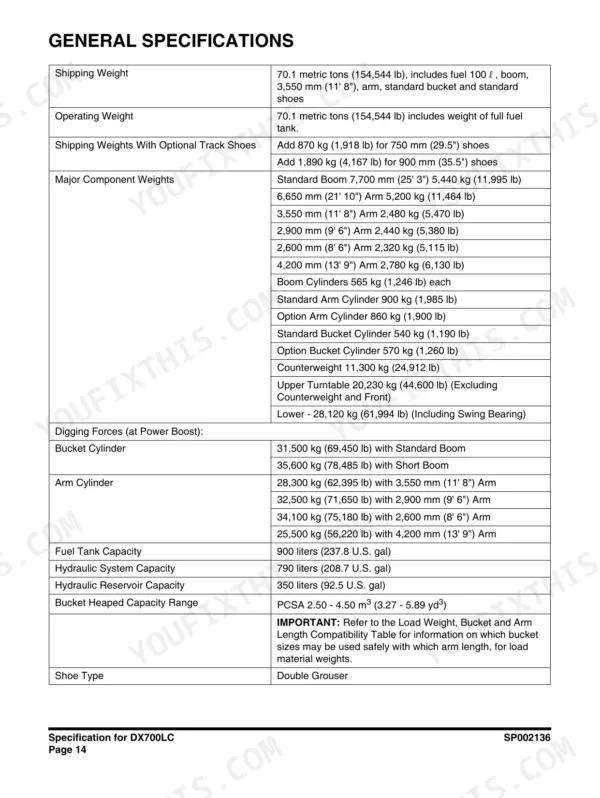
| Fuel tank capacity | 900 liters (237.8 U.S. gal) | p. 66 |
| Hydraulic system capacity | 790 liters (208.7 U.S. gal) | p. 66 |
| Hydraulic reservoir capacity | 350 liters (92.5 U.S. gal) | p. 66 |
| Main relief pressure | 320 kg/cm² (4,551 psi); 350 kg/cm² (4,978 psi) with Pressure Up | p. 72 |
| Tail swing radius | 4,090 mm (13' 5") | p. 63 |
| Counterweight clearance | 1,525 mm (5' 0") | p. 63 |
| Track length | 5,975 mm (19' 7") | p. 63 |
| Tumbler distance | 4,730 mm (15' 6") | p. 63 |
| Shipping length, 7.7 m boom with 3.55 m arm | 13,250 mm (43' 6") | p. 63 |
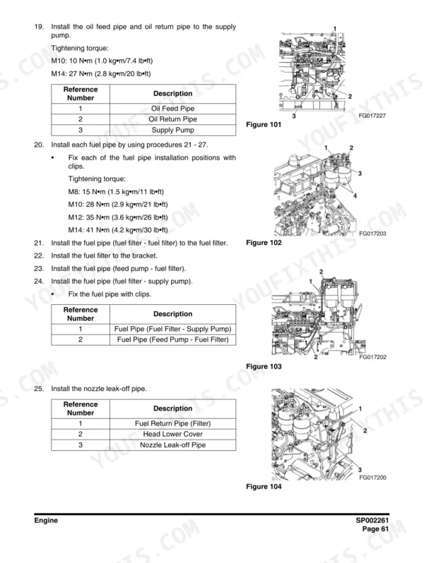
| Oil feed and return pipe torque, M10 | 10 N·m (1.0 kg·m / 7.4 lb ft) | p. 335 |
| Oil feed and return pipe torque, M14 | 27 N·m (2.8 kg·m / 20 lb ft) | p. 335 |
| Fuel pipe torque, M12 | 35 N·m (3.6 kg·m / 26 lb ft) | p. 335 |
Doosan DX700LC Common Problems This Manual Covers
Swing motion is jerky or weak, with grinding noise and growing play in the swing bearing.
Check axial and lateral swing bearing play against limits before anything else, then follow the Swing Motor section's construction and working principle pages and teardown procedure to inspect the reduction gears and bearings. Caught early, this is a bearing job, not a housing replacement.
Manual Section: Hydraulics - Swing Motor p. 525Hydraulic functions slow down, get noisy, or the oil overheats under load.
Work the Hydraulic System Troubleshooting, Testing and Adjustment section step by step: verify main relief at 320 kg/cm2 (350 with Pressure Up, page 72), check for aeration and contamination, then test pump flow. The hydraulic schematic on page 997 shows every circuit so you can isolate the leaking component.
Manual Section: Hydraulics - Hydraulic System Troubleshooting, Testing and Adjustment p. 583Tracks wear unevenly and undercarriage parts like rollers and idlers fail early.
Set track tension to spec using the Track Assembly procedure, then measure links, rollers, idlers and shoes against the wear limits and tolerances tables in the same section. On a 70 tonner with a 5,975 mm track frame, catching wear at the measurement stage is far cheaper than replacing a chain.
Manual Section: Lower Structure and Chassis - Track Assembly p. 641Hard starting, weak charging, or intermittent electrical faults that come and go with weather.
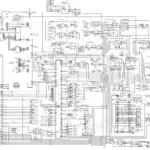
Start with the Engine Starting Circuit pages in the Electrical System section, which walk through the start operation and what happens after start, then trace the suspect circuit on the full electrical schematic (SP002189, page 1125). Most of these faults are corroded grounds and connectors, and the schematic shows exactly where they live.
Manual Section: Electrical System p. 219Frequently Asked Questions
My monitor is showing a fault code. Does this manual tell me what it means?
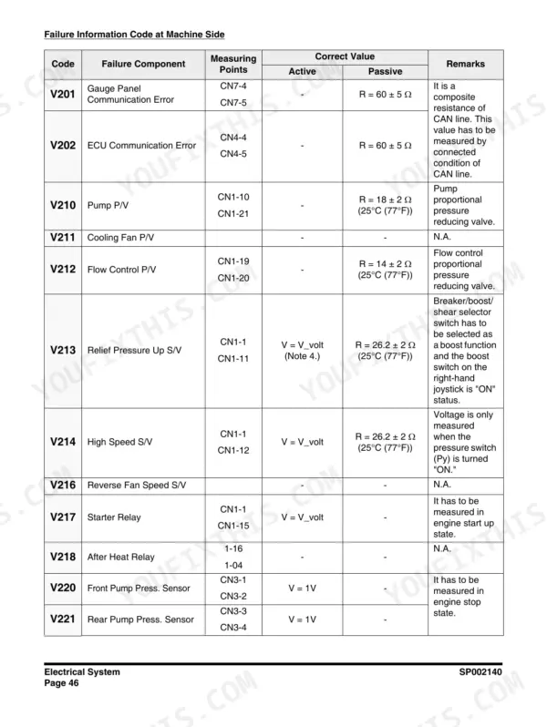
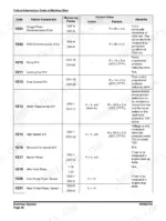
Yes. Page 1046 lists the Failure Information Codes at Machine Side, which run V201 through V232, each matched to a component. For example, V201 is a Gauge Panel Communication Error. Note the format: it is always a V followed by three digits. Look the code up, find the named component, then jump to that component's troubleshooting pages instead of guessing at wiring. p. 1046
How do I clear a fault code on the DX700LC?
These codes flag a real fault in the named component or its circuit, so the honest answer is you clear them by fixing the cause. Use the code list on page 1046 to identify the component, then work the Electrical System section and the full electrical schematic on page 1125 to trace the circuit. Chasing wiring, connectors and grounds this way beats swapping parts on a hunch. p. 69
Can I actually test and set hydraulic pressures with this book?
Yes, that is the strongest part of it. The Hydraulic System Troubleshooting, Testing and Adjustment section gives port locations, test procedures and target values, including main relief at 320 kg/cm2, or 350 kg/cm2 with Pressure Up (page 72). Pair that with the hydraulic schematic on page 997 and you can diagnose a slow or weak function instead of throwing a pump at it. p. 997
The swing has gotten jerky and it grinds. Is the swing drive covered?
Fully. The Swing Motor section includes the instruction manual, specifications, construction and working principle, and teardown. On a machine this size, swing bearing and swing reduction wear is the classic expensive failure, so check play early. The manual gives you the inspection and disassembly detail to tell a worn reduction gear from a bearing on its way out before it takes the housing with it. p. 66
Does it cover the Isuzu engine and the routine service items?
The Engine section covers the 6WG1-TC (469 ps at 1,800 rpm) with general information, service precautions, model reading and engine mechanical work. General Maintenance covers procedures, welding precautions and hydraulic system cleanliness. Fluid capacities are in the spec pages, including the 900 liter fuel tank and 790 liter hydraulic system, so you know exactly what to order before a full service. p. 335






Reviews
There are no reviews yet.