
Part of the Doosan Repair Manuals.
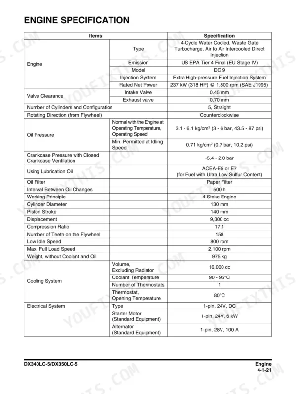
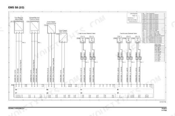
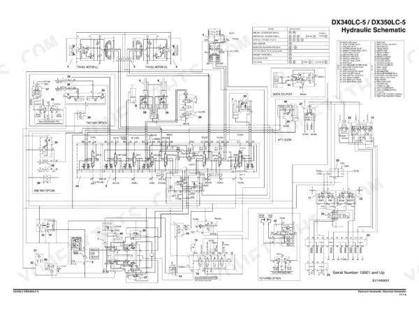
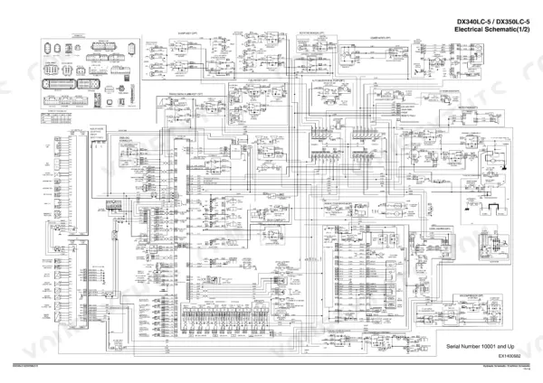
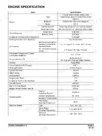
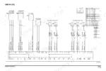
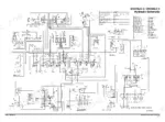
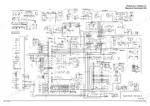
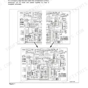
One book, two machines: this is the factory shop manual for the Doosan DX340LC-5 and DX350LC-5 crawler excavators, publication 950106-01001E, 1st Edition April 2014. If you run either one, you are covered. These are Tier 4 Final machines with the Scania-built Doosan DC 9, a five cylinder in-line diesel rated 237 kW (318 HP) at 1,800 rpm - not the DL 06P from the smaller Doosans and not the DC 13 from the bigger ones, so make sure your other references match. Inside: full engine teardown chapters, main pump and main control valve, swing device, travel gear, hydraulic and electrical systems, plus oversize schematic foldouts at pages 1629 to 1631 and six A3 electrical sheets at pages 551 to 556.
Complete the set for your DX340LC-5, DX350LC-5
- Operation & Tests: Doosan DX340LC-5, DX350LC-5 Diagnostic Manual — Wiring Diagrams
What's Inside This Doosan DX340LC-5, DX350LC-5 Manual
| System | Pages | Key Topics |
|---|---|---|
| Safety | 7-74 | Track Excavator Maintenance Safety, Safety Messages, Safe Operation Is Operator's Responsibility, Know Your Machine, Proper Work Tools and Attachments, Pressurized Fluids |
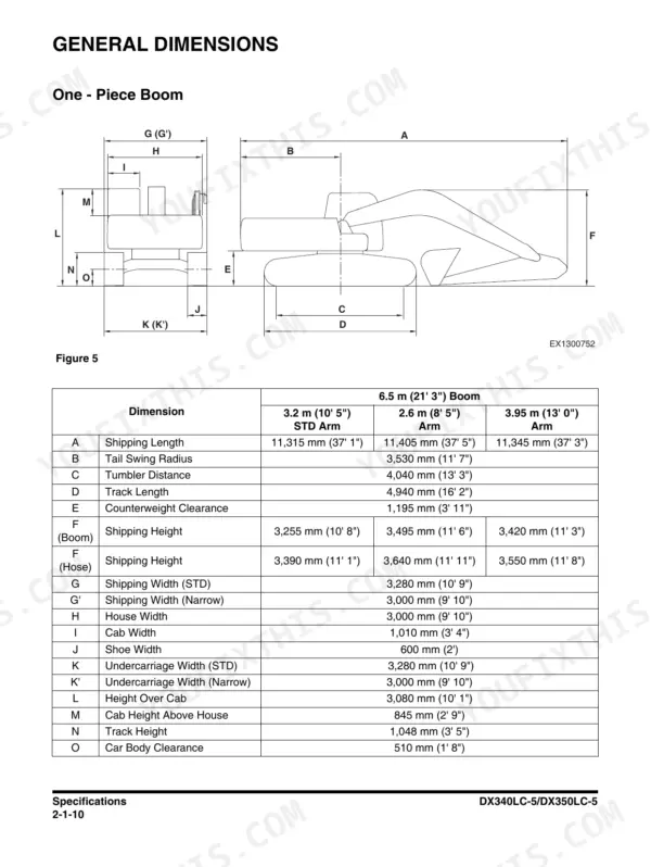
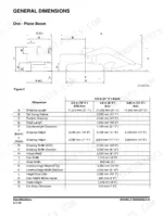
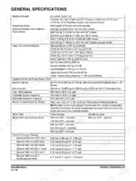
| Specifications and General Maintenance | 75-148 | Specifications, General Description, Component Locations, General Dimensions, One - Piece Boom, Two - Piece Boom |
| Engine - Inspection to Tightening Torques | 149-205 | Engine, Overview, Inspection, Cleaning the Engine, Special Tools, Mounting the Engine in a Universal Stand |
| Engine - Cylinder | 206-259 | Cylinder, Cylinder Head, Valve Mechanism, Cylinder Block, Cylinder Liner, Flywheel Housing |
| Engine - Actuating System and Lubrication System | 260-333 | Actuating System, Camshaft, Connecting Rod, Crankshaft, Flywheel, Piston |
| Engine - Exhaust System | 334-424 | Exhaust System, General Information, T113, Exhaust Temperature Sensor Before Catalytic Converter, T115, NOx Sensor, T131 NOx Sensor, T116, Reductant Pick-Up Unit |
| Engine - Cooling System and Fuel System | 425-489 | Cooling System, Internal Cleaning of Cooling System, Charge Air Cooler, Charge Air Temperature Sensor, Charge Air Pressure Sensor, Coupling Coil for AC Compressor |
| Engine - Electrical System to Engine Coolant Heater (Option) | 490-572 | Electrical System, E44, Control Unit EMS, Control Unit EEC, Engine Speed Sensor, T110 Oil Level Sensor, T111, Fuel Pressure Sensor |
| Upper Structure - Cabin to Fuel Tank | 573-640 | Cabin, Cabin Identification, Roll-Over Protective Structure (ROPS), Removal, Installation, Dimensions of Cabin Glass |
| Upper Structure - Main Pump | 641-790 | Main Pump, Specifications, Overview, Hydraulic Circuit, Parts List, Theory of Operation |
| Upper Structure - Drive Coupling (Main Pump) | 791-802 | Drive Coupling (Main Pump), Specification, Parts List, Section View, Tools, Disassembly |
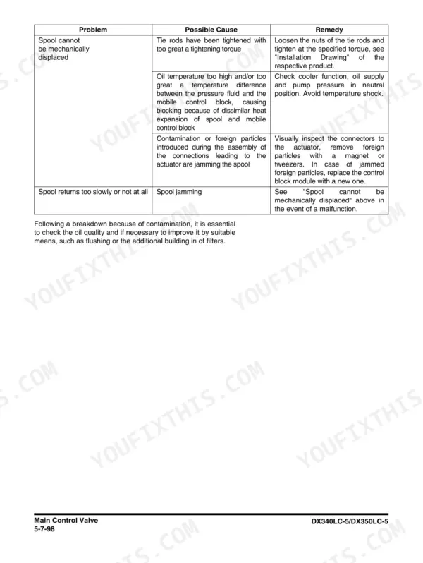
| Upper Structure - Main Control Valve | 803-904 | Main Control Valve, Specification, Overview, Parts List, Theory of Operation, Removal |
| Upper Structure - Swing Device | 905-962 | Swing Device, Specification, Overview, Hydraulics Circuit, Parts List, Theory of Operation |
| Upper Structure - Fan Pump for Oil Cooler | 963-1000 | Fan Pump for Oil Cooler, Specification, Overview, Parts List, Theory of Operation, Maintenance Guidelines |
| Upper Structure - Fan Motor for Oil Cooler to Joystick Valve (Work Lever) | 1001-1058 | Fan Motor for Oil Cooler, Specification, Overview, Parts List and Section View, Precaution, Tools |
| Upper Structure - Travel Control Valve (with Damper) to Two Pump | 1059-1114 | Travel Control Valve (with Damper), Specification, Overview, Parts List, Theory of Operation, Tools and Torques |
| Lower Structure and Chassis | 1115-1242 | Swing Bearing, General Description, Parts List, Maintenance Guidelines, Disassembly, Reassembly |
| Front | 1243-1304 | Boom and Arm, Specifications, One - Piece Boom, Two - Piece Boom, Removal, Arm Removal |
| Hydraulic System | 1305-1382 | General Description, Hydraulic Schematic, Hydraulic Component, Boom Up Operation, Boom Down Operation |
| Electrical System | 1383-1542 | Electrical Supply System, Engine Starting Circuit, Start Operation, After Start, Engine Stop |
| Options | 1543-1624 | One Way, General Description, Theory of Operation, Hydraulic Circuit, Caution for Installation, Installation Procedure |
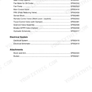
| Schematic | 1625-1631 | Hydraulic Schematic / Electrical Schematic, Hydraulic Schematic, Electrical Schematic |
Quick Reference Specifications
| Specification | Value | Page |
|---|---|---|
| Engine model | Doosan DC 9 (Scania), 5-cylinder in-line, US EPA Tier 4 Final | p. 171 |
| Rated net power | 237 kW (318 HP) @ 1,800 rpm | p. 171 |
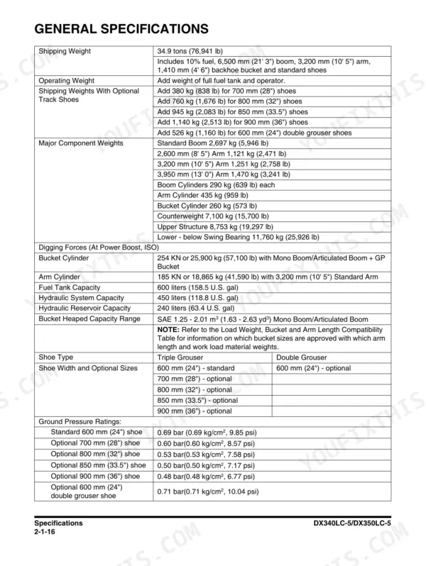
| Shipping weight | 34.9 tons (76,941 lb) | p. 92 |
| Fuel tank capacity | 600 liters (158.5 U.S. gal) | p. 92 |
| Counterweight | 7,100 kg (15,700 lb) | p. 92 |
| Standard boom weight | 2,697 kg (5,946 lb) | p. 92 |
| Optional shoe weight penalty | add 380 kg (838 lb) for 700 mm (28") shoes | p. 92 |
| Tail swing radius | 3,530 mm (11' 7") | p. 86 |
| Track length | 4,940 mm (16' 2") | p. 86 |
| Counterweight clearance | 1,195 mm (3' 11") | p. 86 |
| Undercarriage width, standard | 3,280 mm (10' 9") | p. 86 |
| Undercarriage width, narrow | 3,000 mm (9' 10") | p. 86 |
| Shoe width | 600 mm (2') | p. 86 |
| Height over cab | 3,080 mm (10' 1") | p. 86 |
Doosan DX340LC-5, DX350LC-5 Common Problems This Manual Covers
Hydraulic performance loss, slow cycles, or a function that cuts in and out
Start with the Hydraulic System chapter to understand the circuit, then follow the inspection procedures in the Main Pump and Main Control Valve sections. Contamination and worn rotating group parts are the usual culprits, and the manual gives you the measurements to confirm it before tearing anything down.
Manual Section: Upper Structure - Main Pump / Main Control Valve; Hydraulic System p. 1305Stalling or fuel starvation in cold weather, water in the fuel
The Engine - Cooling System and Fuel System chapter covers the fuel supply from tank to injectors, including the water separator and filters that freeze up when drainage gets skipped. Follow its inspection sequence to find where flow is interrupted, and use the maintenance intervals in the Specifications and General Maintenance chapter to keep it from repeating.
Manual Section: Engine - Cooling System and Fuel System p. 1115Overheating or poor cooling under load
Dust packing the oil cooler and intercooler cores is the common cause on these machines. The Engine - Cooling System and Fuel System chapter handles coolant side inspection, while the Fan Pump and Fan Motor sections cover the hydraulically driven oil cooler fan itself, which has its own failure modes worth checking before you condemn the radiator.
Manual Section: Upper Structure - Fan Pump for Oil Cooler / Fan Motor for Oil Cooler; Engine - Cooling System and Fuel System p. 1383Electrical gremlins: erratic gauges, warning alerts, controls that stop responding
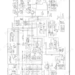
The Electrical System chapter maps the controllers, monitor, connectors, and harness runs, and the oversize schematic foldouts at pages 1629 to 1631 let you trace any circuit end to end. Most faults on a machine this age come down to a chafed wire or corroded connector, and the schematics are how you find which one.
Manual Section: Electrical System; Schematic p. 641Frequently Asked Questions
Does this manual cover both the DX340LC-5 and the DX350LC-5?
Yes, one book covers both machines. Doosan published them together because they share the DC 9 engine, pumps, and most of the upper structure. Whichever badge is on your counterweight, the procedures in here apply, and where the two differ the manual calls it out. p. 171
How do I find out what an error code on the monitor means?
The Electrical System chapter is where diagnostics live in this book. It covers the monitor panel, controllers, connectors, and the wiring behind them, and the schematic foldouts at the back let you trace any circuit a fault points to. This listing does not quote individual code numbers, so I will not pretend to - you read the code off the machine, then use this manual to chase the actual circuit or component behind it. p. 92
The hydraulics feel weak or a function drops out intermittently. Will this manual help?
That is exactly what the Upper Structure chapters are for. Main Pump, Main Control Valve, and Swing Device each get their own section with disassembly, inspection, and assembly steps, and the Hydraulic System chapter ties the circuits together. Most intermittent function loss on these machines traces to contamination or a sticking spool, and the inspection procedures tell you what to measure before you buy parts. p. 1629
Which engine is in these machines, and does the manual cover it in depth?
The Doosan DC 9, built by Scania - five cylinders in line, 237 kW (318 HP) at 1,800 rpm, US EPA Tier 4 Final. The engine gets six full chapter groups here, from tightening torques and cylinder work through the actuating, lubrication, exhaust, cooling, fuel, and electrical systems, including the optional coolant heater. Six A3 electrical sheets sit inside the engine section at pages 551 to 556. p. 86
Are the wiring and hydraulic schematics actually included?
Yes, and they are the real oversize foldouts, not thumbnails. The final Schematic chapter carries them at pages 1629 to 1631, and the engine section adds six A3 electrical sheets at pages 551 to 556. If you have ever tried to trace a wire off a shrunken half page scan, you know why that matters. p. 1383






Reviews
There are no reviews yet.