
Part of the Doosan Repair Manuals.
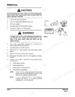
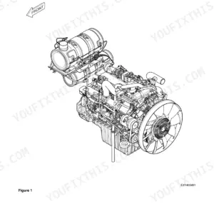
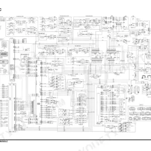
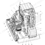
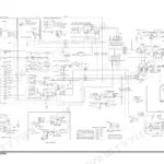
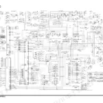
Wrench on a Doosan DX225LCA track excavator? This Doosan DX225LCA service manual PDF (OEM #K1049156E) packs 792 pages of factory shop manual procedures into one download. You get the complete electrical schematic with wiring diagrams, hydraulic schematics for the DX225LC/DX225LCA circuit, and a dedicated hydraulic troubleshooting, testing and adjustment section. Rebuild procedures cover the swing bearing, swing motor, travel motor, main control valve, axial piston pump, track assembly, and the boom, arm, and bucket. Standard torque tables and a full specifications chapter back every job. Set the overload relief valves to 360 kg/cm2 (5,112 psi), and torque the sprocket fitting bolts to 25.7 kg-m before you send it back to the pit. No more chasing pilot-pressure faults with a gauge and a guess. Bookmarked, keyword-searchable, and readable on any device: download it and walk it straight to the machine.
What's Inside This Doosan DX225LCA Manual
| System | Pages | Key Topics |
|---|---|---|
| Safety | 7-52 | Track Excavator Safety |
| Specifications | 53-80 | Specification for DX225LCA |
| General Maintenance | 81-118 | General Maintenance Procedures, Standard Torques |
| Upper Structure | 119-224 | Cabin, Counterweight, Fuel Tank, Fuel Transfer Pump, Swing Bearing, Swing Reduction Gear |
| Lower Structure and Chassis | 225-260 | Track Assembly |
| Engine and Drive Train | 261-274 | Drive Coupling (Main Pump) |
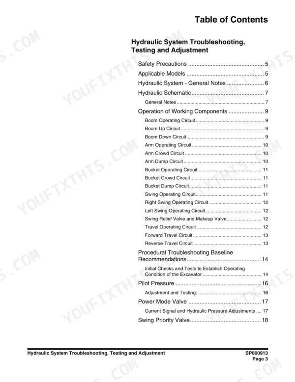
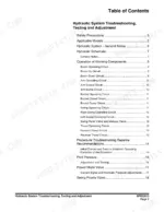
| Hydraulic System Troubleshooting, Testing and Adjustment | 277-310 | Hydraulic System - General Notes, Hydraulic Schematic, General Notes, Operation of Working Components, Boom Operating Circuit, Boom Up Circuit, Boom Down Circuit, Arm Operating Circuit, Arm Crowd Circuit |
| Accumulator | 311-320 | General Description, Specifications, Precharge Pressure, Accumulator Charging with Nitrogen, Bleeding Residual Pilot Pressure |
| Center Joint (Swivel) | 321-334 | Parts List, Troubleshooting, Testing and Adjustment, Inspection, Testing, Disassembly, Reassembly |
| Cylinders | 335-366 | Theory of Operation, Parts List, Special Tools and Materials, Piston Nut, Piston Jig, Steel Bushing Jig, Dust Wiper Jig, Slipper Seal Jig, Slipper Seal Straightening Jig |
| Swing Motor | 367-402 | Operation Manual, Information on Marking, Specifications, Structure and Operational Principles, Cautions, Maintenance Instructions, Disassembly and Assembly, Maintenance |
| Travel Motor | 403-460 | TM40VD Operation Manual, General Specifications, Legend, Basic Structure and Diagram, Operation Principles, Cautions in Use, External Specifications Diagrams, Basic Structure and Diagrams, TM40VD Maintenance Instructions |
| Gear Pump | 461-472 | Single Gear Pump, Disassembly, Reassembly |
| Main Control Valve | 473-540 | Theory of Operation, Parts List, Specifications, Troubleshooting, Testing and Adjustment, Adjustment of Valves, Disassembly, Tolerances), Cleaning |
| Axial Piston Pump | 541-560 | Pump Maintenance, Component Locations, Parts List, Tools, Tightening Torque, Disassembly, Reassembly, Pump Body Maintenance Standards, Change Standards of Worn Parts |
| PTO Server | 561-572 | Pump Maintenance, Disassembly, Reassembly, Maintenance Standards of Pump Body |
| Remote Control Valve (Work Lever / Joystick) | 573-594 | Theory of Operation, Parts List, Specifications, Torques, Tools and Materials, Disassembly, Tolerances), Reassembly, Start-Up Procedures |
| Travel Control Valve (with Damper) | 595-620 | Theory of Operation, Pressure Reducing Valve, Operating Theory of Damper Mechanism, Causes of Faults and Measures, Parts List, Specification, Torques, Removal, Disassembly |
| Solenoid Valve Assembly | 621-636 | Parts List, Functions of 5-Solenoid Valve Assembly Package, Assembly Diagram and Tools Required, Cautions During Disassembly and Reassembly, Solenoid Valve Diagram, Check Points and Solutions for Problems, Assembly Diagram and Tools Reguired, Troubleshooting Guide |
| Breaker EPPR Valve (Opt) | 637-648 | Structure, Numbers and Names of Parts, Functions and Operation, Cautions for Operation, Maintenance Instructions, Maintenance, Disassembly, Assembly |
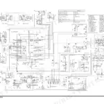
| Hydraulic Schematic (DX225LC/DX225LCA) | 649-655 | Full Hydraulic Circuit Diagram, Component Legend, Pump and Main Control Valve Routing, Circuit Coverage for DX225LC/DX225LCA |
| Electrical System | 656-766 | Electrical Schematic (DX225LCA) |
| Attachments | 767-792 | Boom and Arm, Bucket |
Quick Reference Specifications
| Specification | Value | Page |
|---|---|---|
| Standard 600 mm (24") shoe ground pressure | 0.45 kg/cm2 (6.4 psi) | p. 67 |
| Optional 700 mm (28") shoe ground pressure | 0.39 kg/cm2 (5.55 psi) | p. 67 |
| Overload relief valves | 360 kg/cm2 (5,112 psi) | p. 285 |
| Boom control valve spools secondary pilot pressure | 7 - 9 kg/cm2 (100 - 130 psi) | p. 285 |
| Sprocket Fitting Bolt Tightening Torque | 25.7 ± 4.0 kg•m | p. 418 |
| Coolant Temperature Sensor Resistance | 128 ohms | p. 683 |
| Filter cleaning interval | 500 hours | p. 733 |
| Main Relief Pressure (Normal) | 330 kg/cm2 | p. 73 |
| Main Relief Pressure (Pressure Up) | 350 kg/cm2 | p. 73 |
| Fuel Tank Capacity | 400 liters | p. 67 |
| Hydraulic System Capacity | 240 liters | p. 67 |
| Hydraulic Reservoir Capacity | 140 liters | p. 67 |
Doosan DX225LCA Common Problems This Manual Covers
Doosan DX225LCA hydraulic pressure loss, boom and arm move slowly under load
Test main relief pressure at the pump port with the digging circuit stalled; spec is 330 kg/cm2 normal, 350 kg/cm2 in power boost mode (page 73). If pressure reads low, follow the hydraulic troubleshooting procedures starting to isolate pump, main control valve, or relief valve. Replace the hydraulic filter before condemning the pump.
Manual Section: Hydraulic System TroubleshootingCoolant temperature warning with E02 code and gradual coolant loss under load
Pressure test the cooling system and inspect radiator hoses and the water pump weep hole for seepage. If the gauge spikes with no visible leak, test the coolant temperature sensor; resistance should read 128 ohms (page 683). Clean or replace the air filter on the 500 hour interval shown on page 733, since restriction drives temperatures up.
Manual Section: Electrical System p. 683Tracks slip and throw off despite repeated tensioner adjustment, chain looks stretched
Measure track link pitch across four links with the track under tension; nominal pitch is 190 mm (page 239), and visible stretch beyond that means the chain is finished. Inspect sprocket teeth for hooking and replace worn sprockets together with the chain, torquing the fitting bolts to 25.7 ± 4.0 kg•m (page 418).
Manual Section: Lower Structure and Chassis p. 239Machine mistracks, one side travels slower with grinding noise from final drive
Drain the travel reduction gear oil and inspect it for metal flakes, then refill with 3.3 liters (page 420). Jack up the affected side and compare travel motor speeds in both directions. Check the travel piping for air bubbles and bleed the circuit fully before pulling the motor for teardown.
Manual Section: Travel Motor TroubleshootingSwing motor rotates slowly, upper structure drifts on slopes, gearbox whines during rotation
Drain the swing reduction gear oil and check it for brass or steel debris, then refill with 3.8 liters (page 220). If the oil comes out clean, verify the swing brake fully releases; a dragging brake mimics gear wear and builds heat fast. Metal in the oil means the reduction gear needs a rebuild.
Manual Section: Swing Gearbox TroubleshootingFrequently Asked Questions
How do I clear fault codes on the DX225LCA gauge panel?
To delete memorized past failure records, go to the 'Failure Info' screen in the special menu. Select 'Delete Fail Log' and press the Enter button. You will be prompted to enter a password; input the password using the No. 1-8 switches. If the password is correct, the records will be deleted, and a 'DELETED!!!' message will appear for 3 seconds. p. 700
What is the torque specification for the main pump drive coupling bolts?
The torque specification for the drive coupling bolts (Ta) is 21 - 23 kgf•m (152 - 166 ft lb) for the DX225LC model. p. 272
What is the fuel tank capacity for the DX225LCA?
The fuel tank capacity for the DX225LCA is 400 liters (105.7 U.S. gal). p. 67
What is the procedure for priming the fuel system if the engine does not start?
To prime the fuel system, stop the engine, open the left side door, and loosen the plug on top of the fuel filter head. Unscrew and pump the hand-operated primer pump located by the fuel injection pump until fuel appears at the plug hole. Tighten the plug and continue pumping until strong resistance is felt, then screw the primer pump knob back into the housing. p. 160
What is the recommended interval for changing the gear oil in the travel motor?
The first gear oil change should be performed after 500 operating hours. Subsequent oil changes should be performed every 1000 operating hours or once a year. p. 420
How will I receive this Doosan DX225LCA Service Manual?
You get a 792-page searchable PDF that downloads instantly after checkout. Open it on your laptop, tablet, or phone, and bring it right to the shop floor.
Can I print specific sections of this Doosan DX225LCA Service Manual?
Yes. Print the pages or sections you need for your own shop use. Any standard printer works.






Reviews
There are no reviews yet.