
Part of the Doosan Repair Manuals.
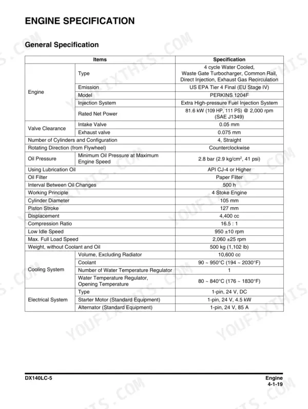
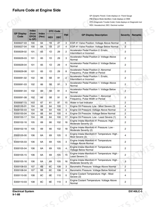
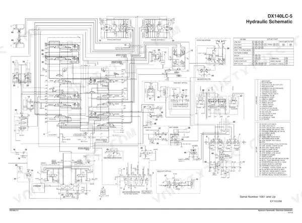
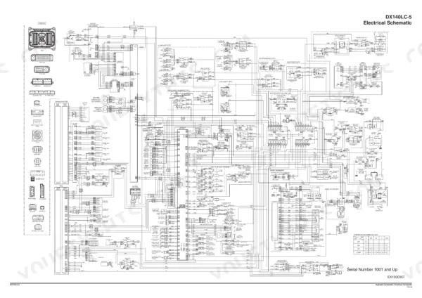
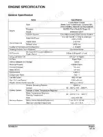
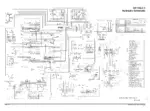
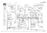
This is the factory shop manual for the Doosan DX140LC-5 crawler excavator, publication 950106-01141E, 1st Edition February 2015. It covers the whole machine: the Perkins 1204F Tier 4 Final engine rated 81.6 kW at 2,000 rpm (page 167), the main pump and control valve with real test specs, swing device, joysticks, cab and ROPS, swing bearing, boom and arm in both one piece and two piece versions, plus full hydraulic and electrical system chapters. The back of the book carries the oversize foldout hydraulic schematic (page 1503) and electrical schematic (page 1504). Fault code tables are printed too, engine ECU codes on page 1328 and panel communication codes on page 1367. This is the book the dealer techs work from.
What's Inside This Doosan DX140LC-5 Manual
| System | Pages | Key Topics |
|---|---|---|
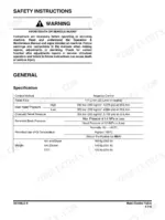
| Safety | 7-74 | Track Excavator Maintenance Safety, Safety Messages, Safe Operation Is Operator's Responsibility, Know Your Machine, Proper Work Tools and Attachments, Pressurized Fluids |
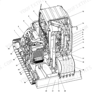
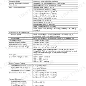
| Specifications and General Maintenance | 75-146 | Specifications, General Description, Component Locations, Overall Dimensions, One - Piece Boom, Two - Piece Boom |
| Engine - General Information to Basic Engine | 147-203 | Engine, Overview, General Information, Major Component Location, Engine Identification, Engine Lifting |
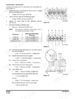
| Engine - Actuating System | 204-281 | Actuating System, Pistons, Rings, And Connecting Rods, Crankshaft, Gears and Timing Gear Case, Camshaft, Rocker Shaft |
| Engine - Lubricant System and Cooling System | 282-317 | Lubricant System, Overview, Engine Oil Pump, Engine Oil Filter, Engine Oil Pan, Engine Oil Pressure - Test |
| Engine - Fuel System | 318-363 | Fuel System, Overview, High-Pressure Fuel System, Water Separator & Pre Fuel Filter (Fuel Prefilter), Main Fuel Filter, Fuel Injection Pump |
| Engine - Air Inlet and Exhaust System | 364-442 | Air Inlet and Exhaust System, Exhaust System, Clean Emissions Module (Diesel Oxidation Catalyst (DOC) and Selective Catalytic Reduction (SCR) System), DEF Dosing Control System |
| Engine - Electrical System and Engine Coolant Heater (Option) | 443-508 | Electrical System, Electrical Control System, Sensor Locations for the Engine, Sensor Locations for the Clean Emissions Module, Electronic Control Module (ECM), Electric Component - Remove and Install |
| Upper Structure - Cabin | 509-536 | Cabin, Cabin Identification, Roll-Over Protective Structure (ROPS), Removal, Installation, Completing Work |
| Upper Structure - Counterweight to Fuel Tank | 537-580 | Counterweight, Warning for Counterweight and Front Attachment Removal, Removal, Installation, Hydraulic Oil Tank, Specification |
| Upper Structure - Main Pump and Drive Coupling (Main Pump) | 581-650 | Main Pump, Axial Piston Pump, General Description, Specifications, Overview, Hydraulic Circuit |
| Upper Structure - Main Control Valve | 651-730 | Main Control Valve, Specification, Overview, Parts List, Theory of Operation, Cautions for Operation |
| Upper Structure - Swing Device | 731-786 | Swing Device, Specification, Overview, Parts List, Theory of Operation, Cautions for Operation |
| Upper Structure - Joystick Valve (Work Lever) | 787-818 | Joystick Valve (Work Lever), Specifications, Overview, Parts List, Theory of Operation, Tools and Torques |
| Upper Structure - Dozer Joystick Valve (Option) and Travel Control Valve (with Damper) | 819-872 | Dozer Joystick Valve (Option), Specifications, Overview, Hydraulic Circuit, Parts List, Theory of Operation |
| Upper Structure - Solenoid Valve to One Spool Valve(Rotating) | 873-930 | Solenoid Valve, Specification, Overview, Parts List, Theory of Operation, Disassembly and Reassembly |
| Lower Structure and Chassis | 931-1092 | Swing Bearing, General Description, Parts List, Maintenance Guidelines, Disassembly, Reassembly |
| Front | 1093-1158 | Boom and Arm, Specifications, One - Piece Boom, Two - Piece Boom, Removal, Arm Removal |
| Hydraulic System | 1159-1238 | General Description, Hydraulic Schematic, Hydraulic Component and Oil Flow, Hydraulic Components, Main Oil Circuit |
| Electrical System | 1239-1406 | Electrical Supply System, Engine Starting Circuit, Start Operation, After Start, Engine Stop |
| Options | 1407-1498 | One Way, General Description, Theory of Operation, Hydraulic Circuit, Caution for Installation, Installation Procedure |
| Schematic | 1499-1504 | Hydraulic Schematic/ Electrical Schematic |
Quick Reference Specifications
| Specification | Value | Page |
|---|---|---|
| Engine model | Perkins 1204F, US EPA Tier 4 Final (EU Stage IV) | p. 167 |
| Rated power | 81.6 kW @ 2,000 rpm | p. 167 |
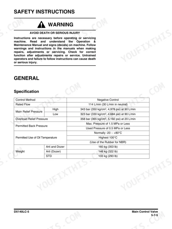
| Main pump rated flow | 114 L/min (30 L/min in neutral) | p. 655 |
| Main relief pressure, high | 343 bar (350 kg/cm², 4,978 psi) at 90 L/min | p. 655 |
| Main relief pressure, low | 323 bar (330 kg/cm², 4,684 psi) at 90 L/min | p. 655 |
| Overload relief pressure | 358 bar (365 kg/cm², 5,192 psi) at 20 L/min | p. 655 |
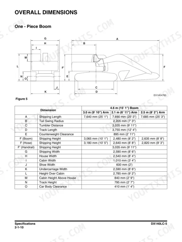
| Tail swing radius | 2,205 mm (7' 3") | p. 86 |
| Counterweight clearance | 895 mm (2' 11") | p. 86 |
| Track length | 3,755 mm (12' 4") | p. 86 |
| Undercarriage width | 2,590 mm (8' 6") | p. 86 |
| Shoe width | 600 mm (2') | p. 86 |
| Height over cabin | 2,785 mm (9' 2") | p. 86 |
| Shipping length | 7,640 mm (25' 1") | p. 86 |
Doosan DX140LC-5 Common Problems This Manual Covers
Digging functions go slow, weak or jerky under load and the hydraulic oil runs hot
Test before you condemn the pump. The Main Pump chapter gives rated flow of 114 L/min and page 655 lists relief settings, 343 bar (350 kg/cm2, 4,978 psi) high and 323 bar (330 kg/cm2, 4,684 psi) low, so you can gauge the circuit and separate pump wear from a tired relief, aeration or plugged cooler.
Manual Section: Upper Structure - Main Pump and Drive Coupling (Main Pump) p. 655Engine speed will not respond to the dial and the power mode selector does nothing
This is a wiring and controller chase, not an engine teardown. Work the Electrical System chapter from the speed control dial through fuses, harness connectors and the controller circuits, checking each connection point in order. Most of these come down to a corroded connector or blown fuse, not a dead controller, so verify cheap parts first.
Manual Section: Electrical System p. 1223Fault lamp on with an engine code, machine derates or DEF system complains
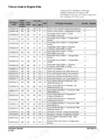
Pull the code and read it against the engine ECU tables starting on page 1328, codes in the E000027-03 format. The engine electrical chapter maps sensor locations for both the engine and the Clean Emissions Module, plus ECM removal and install, so you test the actual sensor the code names instead of swapping parts blind.
Manual Section: Engine - Electrical System and Engine Coolant Heater (Option) p. 1035Battery goes flat overnight or the machine cranks slow every cold morning
The electrical chapter covers the supply system and the complete starting circuit, start operation, after start and engine stop, step by step. Follow it to check terminals, alternator belt and charging output in sequence before buying a battery. A loose ground or glazed belt kills more batteries on these machines than actual cell failure does.
Manual Section: Electrical System p. 219Frequently Asked Questions
My DX140LC-5 is showing a fault code. Does this manual tell me what it means?
Yes, and it separates the two code families this machine actually uses. Engine ECU codes look like E000027-03, a six digit number with an FMI style suffix, and those tables start on page 1328. Panel and communication codes are the short V series, like V201 and V202, listed on page 1367. Do not mix the two families up when you search, they live in different tables and point at different controllers. p. 1328
How do I clear a fault code or reset the monitor alarm on this machine?
Most codes on this excavator clear themselves once the actual fault condition is gone, so the honest answer is: diagnose first. The Electrical System chapter walks the control circuits, sensor locations and the ECM, so you can trace whether a code is a real failure or a wiring/connector issue. Chasing a reset without fixing the cause just brings the lamp back, usually at the worst time. p. 655
Hydraulics feel slow and weak. Does the manual give real pressure numbers to test against?
It does. Main relief is printed as 343 bar (350 kg/cm2, 4,978 psi) high and 323 bar (330 kg/cm2, 4,684 psi) low, both at 90 L/min, with overload relief at 358 bar (365 kg/cm2, 5,192 psi) at 20 L/min, all on page 655. Pump rated flow is 114 L/min. Gauge the machine, compare to the page, and you know in an hour whether it is the pump, a relief or contamination. p. 1503
Which engine does this cover, is it really a Perkins?
Yes, the DX140LC-5 runs a Perkins 1204F, US EPA Tier 4 Final / EU Stage IV, not a Doosan or any other unit. The manual has six engine chapters covering pistons, crank, cam, oil pump, the high pressure fuel system, filters, injection pump, and the Clean Emissions Module with the DOC, SCR and DEF dosing control system. That aftertreatment section matters, because emissions faults are what park these machines. p. 167
Are the full wiring and hydraulic schematics in the book?
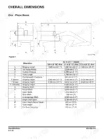
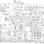
Yes, as oversize foldouts in the final Schematic chapter: the hydraulic schematic is page 1503 and the electrical schematic is page 1504. Each system chapter also has its own circuit drawings, so you can follow one function, say swing or travel, without unfolding the whole machine. For lifting and hauling, the dimension tables on page 86 give shipping length 7,640 mm and height over cabin 2,785 mm. p. 86






Reviews
There are no reviews yet.