
Part of the Doosan Repair Manuals.
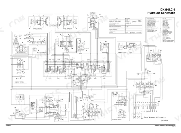
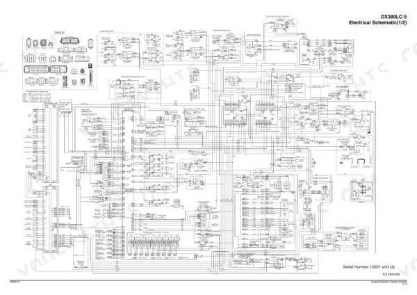
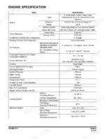
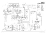
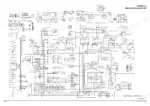
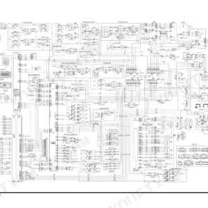
This is the factory shop manual Doosan issued for the DX380LC-5 crawler excavator, 2014 edition, publication 950106-01236E. It covers the machine the way the dealer techs work on it: full teardown of the Scania-built Doosan DC 9 engine (237 kW (318 HP) @ 1,800 rpm, Tier 4 Final per page 169), cylinder head and liner work, crank and piston service, plus the aftertreatment hardware Tier 4 brought with it - NOx sensors, exhaust temperature sensor, reductant pick-up unit. Upper structure chapters walk the main pump, main control valve, swing device and fan drive through specs, theory of operation, disassembly and reassembly. The book closes with oversize foldout schematics: hydraulic on page 1645, electrical across two sheets on pages 1649 and 1650.
What's Inside This Doosan DX380LC-5 Manual
| System | Pages | Key Topics |
|---|---|---|
| Safety | 7-74 | Track Excavator Maintenance Safety, Safety Messages, Safe Operation Is Operator's Responsibility, Know Your Machine, Proper Work Tools and Attachments, Pressurized Fluids |
| Specifications and General Maintenance | 75-146 | Specifications, General Description, Component Locations, General Dimensions, Working Range, General Specifications |
| Engine - Inspection to Tightening Torques | 147-203 | Engine, Overview, Inspection, Cleaning the Engine, Special Tools, Mounting the Engine in a Universal Stand |
| Engine - Cylinder | 204-257 | Cylinder, Cylinder Head, Valve Mechanism, Cylinder Block, Cylinder Liner, Flywheel Housing |
| Engine - Actuating System and Lubrication System | 258-331 | Actuating System, Camshaft, Connecting Rod, Crankshaft, Flywheel, Piston |
| Engine - Exhaust System | 332-422 | Exhaust System, General Information, T113, Exhaust Temperature Sensor Before Catalytic Converter, T115, NOx Sensor, T131 NOx Sensor, T116, Reductant Pick-Up Unit |
| Engine - Cooling System and Fuel System | 423-487 | Cooling System, Internal Cleaning of Cooling System, Charge Air Cooler, Charge Air Temperature Sensor, Charge Air Pressure Sensor, Coupling Coil for AC Compressor |
| Engine - Electrical System and Engine Coolant Heater (Option) | 488-564 | Electrical System, E44, Control Unit EMS, Control Unit EEC, Engine Speed Sensor, T110 Oil Level Sensor, T111, Fuel Pressure Sensor |
| Upper Structure - Cabin to Fuel Tank | 565-632 | Cabin, Cabin Identification, Roll-Over Protective Structure (ROPS), Removal, Installation, Completing Work |
| Upper Structure - Main Pump | 633-782 | Main Pump, Specifications, Overview, Hydraulic Circuit, Parts List, Theory of Operation |
| Upper Structure - Drive Coupling (Main Pump) | 783-794 | Drive Coupling (Main Pump), Specification, Parts List, Section View, Tools, Disassembly |
| Upper Structure - Main Control Valve | 795-896 | Main Control Valve, Specification, Overview, Parts List, Theory of Operation, Removal |
| Upper Structure - Swing Device | 897-954 | Swing Device, Specification, Overview, Hydraulics Circuit, Parts List, Theory of Operation |
| Upper Structure - Fan Pump for Oil Cooler | 955-992 | Fan Pump for Oil Cooler, Specification, Overview, Parts List, Theory of Operation, Maintenance Guidelines |
| Upper Structure - Fan Motor for Oil Cooler to Travel Control Valve (with Damper) | 993-1070 | Fan Motor for Oil Cooler, Specification, Overview, Parts List and Section View, Precaution, Tools |
| Upper Structure - Solenoid Valve to One Spool Valve (Rotating) | 1071-1122 | Solenoid Valve, Specification, Overview, Parts List, Theory of Operation, Disassembly and Reassembly |
| Lower Structure and Chassis | 1123-1260 | Swing Bearing, General Description, Parts List, Maintenance Guidelines, Disassembly, Reassembly |
| Front | 1261-1320 | Boom and Arm, Specifications, Removal, Arm Removal, Boom Removal, Installation |
| Hydraulic System | 1321-1398 | General Description, Hydraulic Schematic, Hydraulic Component, Boom Up Operation, Boom Down Operation |
| Electrical System | 1399-1558 | Electrical Supply System, Engine Starting Circuit, Start Operation, After Start, Engine Stop |
| Options | 1559-1640 | One Way, General Description, Theory of Operation, Hydraulic Circuit, Caution for Installation, Installation Procedure |
| Schematic | 1641-1650 | Hydraulic Schematic / Electrical Schematic |
Quick Reference Specifications
| Specification | Value | Page |
|---|---|---|
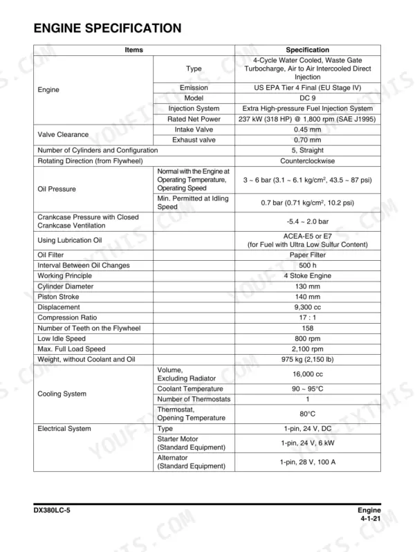
| Engine model | Doosan DC 9 (Scania), US EPA Tier 4 Final (EU Stage IV) | p. 169 |
| Rated net power | 237 kW (318 HP) @ 1,800 rpm (SAE J1995) | p. 169 |
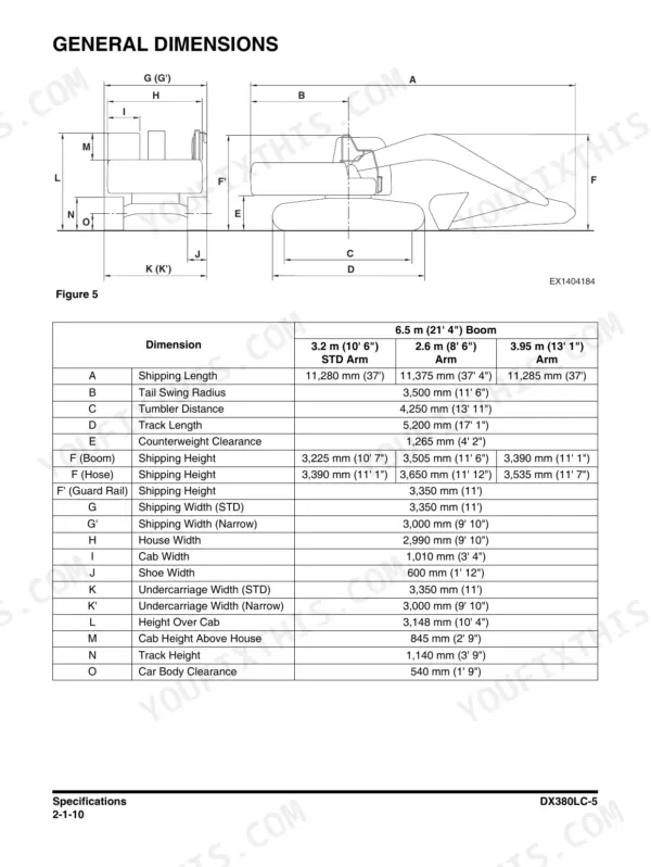
| Tail swing radius | 3,500 mm (11' 6") | p. 86 |
| Track length | 5,200 mm (17' 1") | p. 86 |
| Counterweight clearance | 1,265 mm (4' 2") | p. 86 |
| Undercarriage width, standard | 3,350 mm (11') | p. 86 |
| Undercarriage width, narrow | 3,000 mm (9' 10") | p. 86 |
| Shoe width | 600 mm (1' 12") | p. 86 |
| Height over cab | 3,148 mm (10' 4") | p. 86 |
Doosan DX380LC-5 Common Problems This Manual Covers
Engine cranks but will not start, or starting is hit and miss
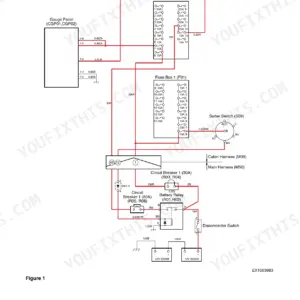
Work the Engine Starting Circuit procedures in the Electrical System chapter, which cover start operation, after start behavior and engine stop. Check battery terminals, grounds and harness condition against the electrical schematic on pages 1649 and 1650 before condemning the starter or control units.
Manual Section: Electrical System p. 1305Slow cylinder movement, overheating hydraulic oil, or a whining main pump
Start with the Main Pump section under Upper Structure: it gives specifications, the hydraulic circuit, theory of operation and a full parts list, so you can pressure test against printed values and decide between contamination flush, valve work or a pump rebuild.
Manual Section: Upper Structure - Main Pump p. 1115Jerky swing, grinding noise during rotation, or no swing at all
The Swing Device section covers specification, hydraulic circuit, theory of operation and complete disassembly and reassembly, which is where worn gears and failing bearings show up. If play is in the turntable itself, the Swing Bearing section under Lower Structure and Chassis has its own removal and maintenance guidelines.
Manual Section: Upper Structure - Swing Device p. 1383Down on power, running hot, or burning more fuel than it should
The Cooling System and Fuel System chapter covers internal cleaning of the cooling system, the charge air cooler, and the charge air temperature and pressure sensors. On a Tier 4 machine these sensors and a plugged cooler cause power loss more often than the injectors do, so check them first.
Manual Section: Engine - Cooling System and Fuel System p. 641Frequently Asked Questions
How do I diagnose fault codes and warning alarms on a DX380LC-5?
The Electrical System chapter documents the control units (E44 EMS and the EEC), the engine speed, oil level and fuel pressure sensors, and the starting and stop circuits, which is where code diagnosis actually happens on this machine. Trace any suspect circuit against the full electrical schematic printed on pages 1649 and 1650. The manual shows you where the sensors live and how the circuits should read; work from there rather than guessing at a code list. p. 169
Does it cover the Tier 4 Final aftertreatment system?
Yes. This is a US EPA Tier 4 Final / EU Stage IV machine (page 169), and the Exhaust System chapter covers the parts that fail on these: the exhaust temperature sensor before the catalytic converter, both NOx sensors, and the reductant pick-up unit. If the machine is derating or throwing emissions warnings, this chapter is where you start. p. 86
Can I rebuild the swing device and main pump with this manual?
Yes, both get full sections in the Upper Structure chapters: specifications, hydraulic circuit, parts list, theory of operation, then step-by-step disassembly and reassembly. The swing bearing itself is handled separately under Lower Structure and Chassis with its own maintenance guidelines. These are the two jobs shops buy this book for most often. p. 1645
Are the full hydraulic and electrical schematics included?
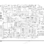
Yes, in the final Schematic chapter as oversize foldouts: the complete hydraulic schematic on page 1645 and the electrical schematic printed as two sheets on pages 1649 and 1650. The Hydraulic System chapter also walks individual operations like boom up and boom down through the circuit so you can follow oil flow function by function. p. 1383
Does it have the dimensions I need for transport and site planning?
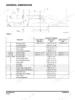
Yes, on page 86: tail swing radius 3,500 mm (11' 6"), track length 5,200 mm (17' 1"), height over cab 3,148 mm (10' 4"), counterweight clearance 1,265 mm (4' 2"), and undercarriage width in both standard 3,350 mm (11') and narrow 3,000 mm (9' 10") gauge. p. 1649







Reviews
There are no reviews yet.