
Part of the Doosan Repair Manuals.
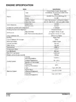
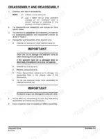
The N in DX235NLC-5 means narrow undercarriage: 2,540 mm (8' 4") wide with 500 mm (1' 8") shoes, built to travel on a lowboy and squeeze into tight rights of way where a standard car body will not fit. This 2015 factory shop manual (publication 950106-01115E, 1st Edition) covers the Tier 4 Final machine with the Doosan DL 06P engine rated 167 HP (169 PS) @ 1,800 rpm. Inside: full teardown and rebuild procedures for the main pump, main control valve, swing device, travel valve and joystick valves, boom and arm removal for both one-piece and two-piece booms, the electrical supply and starting circuits, and oversize foldout hydraulic and electrical schematics at the back.
What's Inside This Doosan DX235NLC-5 Manual
| System | Pages | Key Topics |
|---|---|---|
| Safety | 7-74 | Track Excavator Maintenance Safety, Safety Messages, Safe Operation Is Operator's Responsibility, Know Your Machine, Proper Work Tools and Attachments, Pressurized Fluids |
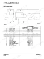
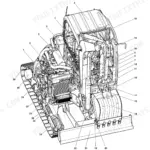
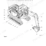
| Specifications | 75-108 | General Description, Component Locations, Overall Dimensions, One - Piece Boom, Two - Piece Boom |
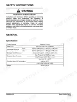
| General Maintenance | 109-146 | General Maintenance Instructions, Welding Precautions and Instructions, Hydraulic System - General Precautions, Maintenance Service and Repair Procedure, General Precautions, Hydraulic System Cleanliness and Oil Leaks |
| Engine | 147-328 | Overview, General Information, General Description, Engine Maintenance, Inspection and Repair of the Engine |
| Upper Structure - Cabin | 329-356 | Cabin, Cabin Identification, Roll-Over Protective Structure (ROPS), Removal, Installation, Completing Work |
| Upper Structure - Counterweight and Hydraulic Oil Tank | 357-384 | Counterweight, Warning for Counterweight and Front Attachment Removal, Removal, Installation, Hydraulic Oil Tank, Specification |
| Upper Structure - Fuel Tank | 385-398 | Fuel Tank, Specification, Parts List, Removal, Installation, Completing Work |
| Upper Structure - Main Pump | 399-464 | Main Pump, Axial Piston Pump, Specifications, Overview, Parts List, Theory of Operation |
| Upper Structure - Drive Coupling (Main Pump) | 465-476 | Drive Coupling (Main Pump), Specification, Parts List, Section View, Tools, Disassembly |
| Upper Structure - Main Control Valve | 477-568 | Main Control Valve, Specification, Overview, Parts List, Theory of Operation, Cautions for Operation |
| Upper Structure - Swing Device | 569-630 | Swing Device, Specification, Overview, Parts List, Theory of Operation, Cautions for Operation |
| Upper Structure - Joystick Valve (Work Lever) | 631-662 | Joystick Valve (Work Lever), Specifications, Overview, Parts List, Theory of Operation, Tools and Torques |
| Upper Structure - Travel Control Valve (with Damper) | 663-690 | Travel Control Valve (with Damper), Specification, Overview, Parts List, Theory of Operation, Tools and Torques |
| Upper Structure - Solenoid Valve to Accumulator | 691-718 | Solenoid Valve, Specification, Overview, Parts List, Theory of Operation, Disassembly and Reassembly |
| Upper Structure - Gear Pump (Rotating) | 719-732 | Gear Pump (Rotating), Specification, Overview, Location, Parts List, Single Gear Pump |
| Upper Structure - One Spool Valve(Rotating) | 733-748 | One Spool Valve(Rotating), Specification, Overview, Theory of Operation, Disassembly and Assembly, General Cautions |
| Lower Structure and Chassis | 749-886 | Swing Bearing, General Description, Parts List, Maintenance Guidelines, Disassembly, Reassembly |
| Front | 887-948 | Boom and Arm, Specifications, One - Piece Boom, Two - Piece Boom, Removal, Arm Removal |
| Hydraulic System | 949-1030 | General Description, Hydraulic Schematic, Hydraulic Component and Oil Flow, Hydraulic Components, Main Oil Circuit |
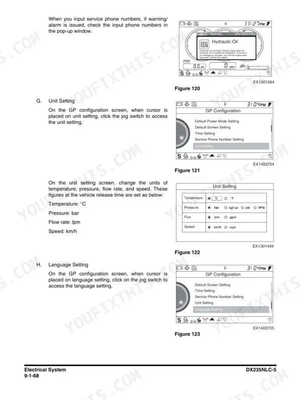
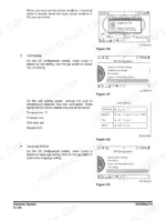
| Electrical System | 1031-1222 | Electrical Supply System, Engine Starting Circuit, Start Operation, After Start, Engine Preheating System |
| Options | 1223-1314 | One Way, General Description, Theory of Operation, Hydraulic Circuit, Caution for Installation, Installation Procedure |
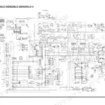
| Schematic | 1315-1320 | Hydraulic Schematic / Electrical Schematic |
Quick Reference Specifications
| Specification | Value | Page |
|---|---|---|
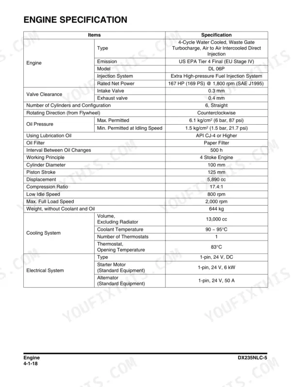
| Engine model | Doosan DL 06P, US EPA Tier 4 Final (EU Stage IV) | p. 166 |
| Rated net power | 167 HP (169 PS) @ 1,800 rpm (SAE J1995) | p. 166 |
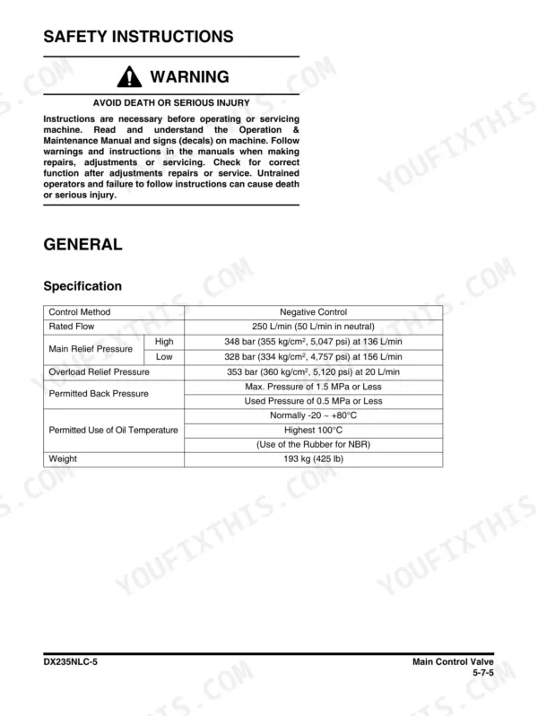
| Main relief pressure | high 348 bar (355 kg/cm², 5,047 psi) at 136 L/min; low 328 bar | p. 481 |
| Main pump rated flow | 250 L/min (50 L/min in neutral) | p. 481 |
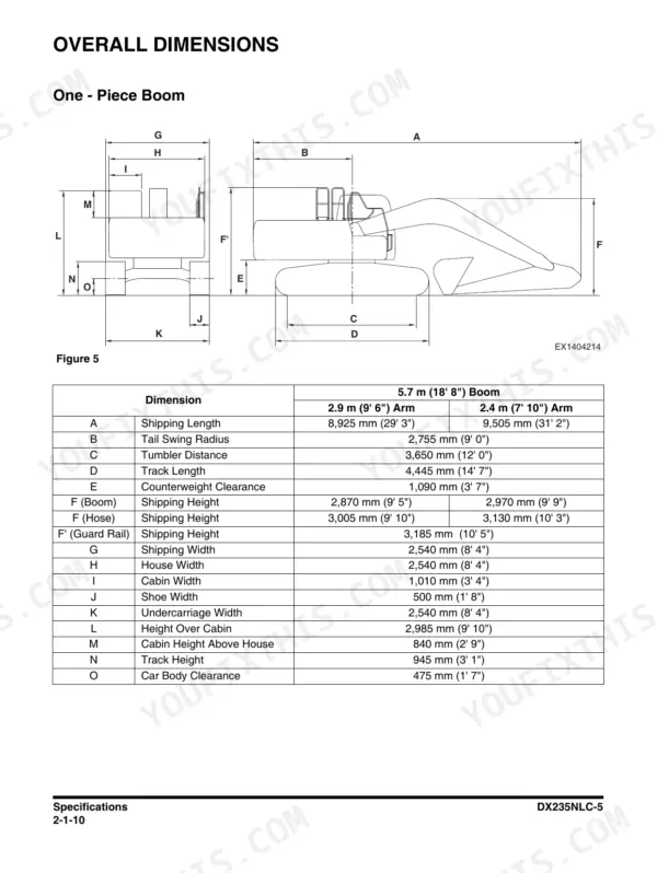
| Tail swing radius | 2,755 mm (9' 0") | p. 86 |
| Counterweight clearance | 1,090 mm (3' 7") | p. 86 |
| Track length | 4,445 mm (14' 7") | p. 86 |
| Undercarriage width | 2,540 mm (8' 4") | p. 86 |
| Shoe width | 500 mm (1' 8") | p. 86 |
| Shipping length | 8,925 mm (29' 3") | p. 86 |
| Height over cabin | 2,985 mm (9' 10") | p. 86 |
| Car body clearance | 475 mm (1' 7") | p. 86 |
Doosan DX235NLC-5 Common Problems This Manual Covers
Weak, slow or dead hydraulic functions that never reach full pressure
Start with a gauge, not a parts order. Check main relief against the printed 348 bar (355 kg/cm2, 5,047 psi) spec on page 481, then work through the Main Pump chapter's theory of operation and the Main Control Valve section to isolate pump, relief or spool problems.
Manual Section: Upper Structure - Main Pump / Main Control Valve p. 481Engine overheating under load or hard starting
The Engine chapter covers the DL 06P from general description through maintenance, inspection and repair, including the cooling side where a slipping belt or weak water pump drive usually hides. For no-start conditions, the Electrical System chapter walks the starting circuit, start operation, after-start behavior and the preheating system step by step.
Manual Section: Engine / Electrical System p. 1229Jerky or noisy swing and travel, loss of power in one function
The Swing Device chapter gives specification, parts list, theory of operation and operating cautions for chasing worn gears and bearings, while the Travel Control Valve (with Damper) section covers the valve that smooths travel response. The Joystick Valve section handles the pilot side if commands feel inconsistent at the lever.
Manual Section: Upper Structure - Swing Device / Travel Control Valve (with Damper) p. 1035Contaminated hydraulic oil, overheating oil or repeat component failures
Dirty oil kills this machine's pumps and valves faster than hours do. The General Maintenance chapter's section on Hydraulic System Cleanliness and Oil Leaks lays out precautions for opening the system, and the Hydraulic Oil Tank section under Upper Structure covers the tank itself, its specification and service access.
Manual Section: General Maintenance - Hydraulic System Cleanliness and Oil Leaks p. 219Frequently Asked Questions
My DX235NLC-5 is throwing an EPOS trouble code. Will this manual help me chase it down?
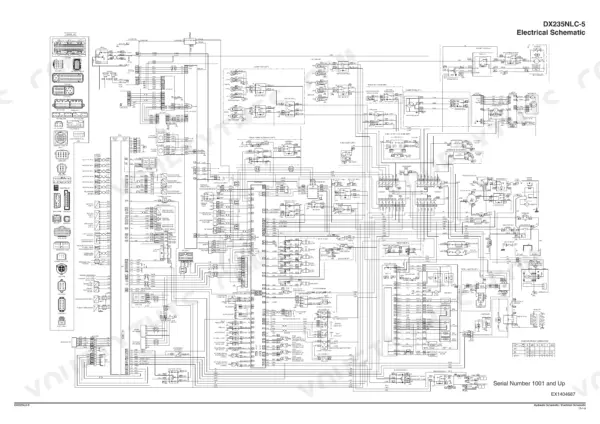
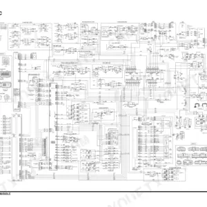
Yes, this is the book for that job. The Electrical System chapter covers the supply system, starting circuit, preheating and monitor wiring, and the full electrical schematic sits as a foldout on page 1320 so you can trace the actual circuit instead of guessing. The manual's diagnostic approach also tells you what to check once codes are cleared: engine speed, pilot pressure, individual relief pressures and the power boost circuit. It does not hand you a magic reset button, because half these codes come back until you fix the wiring or pressure problem underneath. p. 166
Hydraulics feel weak and slow under load. What numbers do I test against?
The ones printed in this book. Main relief is 348 bar (355 kg/cm2, 5,047 psi) at 136 L/min on the high setting and 328 bar on the low setting, with main pump rated flow of 250 L/min and 50 L/min in neutral, all on page 481. Put a gauge on it, compare, then use the Main Pump and Main Control Valve chapters, each with a full parts list and theory of operation, to find what is bleeding your pressure off. p. 481
Does it include the complete hydraulic and electrical schematics?
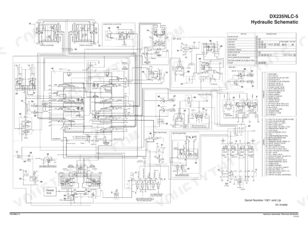
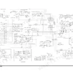
Both, as full oversize foldouts in the final Schematic chapter: hydraulic schematic on page 1319, electrical schematic on page 1320. The Hydraulic System chapter also walks the main oil circuit component by component, which is what you actually want when you are tracing why oil is going somewhere it should not. p. 1320
My machine has the two-piece boom. Am I covered?
Yes. The Specifications chapter lists dimensions for both one-piece and two-piece boom configurations, and the Front chapter gives removal and installation procedures for boom and arm on both versions. Counterweight removal warnings and procedure are in their own Upper Structure section, which matters because boom work and counterweight work on this machine are connected jobs. p. 86
Is this the right book for my serial number and engine?
This is the 2015 1st Edition shop manual for the DX235NLC-5 with the Doosan DL 06P engine, US EPA Tier 4 Final / EU Stage IV. Quick sanity checks against your machine: tail swing radius 2,755 mm (9' 0"), track length 4,445 mm (14' 7"), undercarriage width 2,540 mm (8' 4"), shipping length 8,925 mm (29' 3"), height over cabin 2,985 mm (9' 10"). If your undercarriage is wider than 2,540 mm, you have the standard LC machine and a different book. p. 1319






Reviews
There are no reviews yet.