Part of the Doosan Repair Manuals.
The ZF transmission chapter carries the heaviest diagnostic load in this DL550-3 shop manual. It covers the 4WG-310 powershift with torque converter, the optional 5WG and the full TCU fault code table. Each code lists its meaning, how the TCU reacts and the steps to repair it.
The rest of the machine is covered too. That means the Scania DC13 Tier 4i with XPI injection, the ZF Multitrac axles and driveshaft, the wet disc service brakes and the SAHR parking brake. Steering, the main pump, the loader valve, the load isolation system and both the hydraulic and electrical schematics are also inside.
The chapters run system by system. When a T code shows on the display, you can go straight to the ZF table without paging through the engine and brake chapters.
What's Inside This Doosan DL550-3 Manual
| System | Pages | Key Topics |
|---|---|---|
| Safety | 7-72 | Wheel Loader Safety Precautions, Operation and Maintenance Warnings |
| Specifications | 73-90 | General Specifications, Engine Performance, Working Range and Dimensions for the DL550-3 |
| General Maintenance | 91-128 | General Maintenance Instructions, Standard Torques |
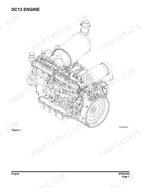
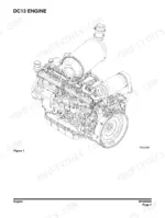
| Engine | 129-360 | Scania DC13 Engine Service, Engine Coolant Heater (Option) |
| Transmission and Torque Converter | 361-672 | ZF 4WG-310 Power Shift Transmission and ZF 5WG (Option) with Torque Converter |
| Transmission Error Codes (ZF) | 673-702 | TCU Modes, Table of ZF Fault Codes with Meaning, TCU Reaction and Possible Steps to Repair |
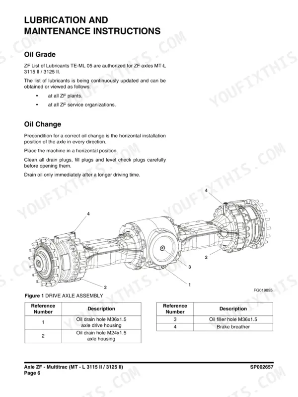
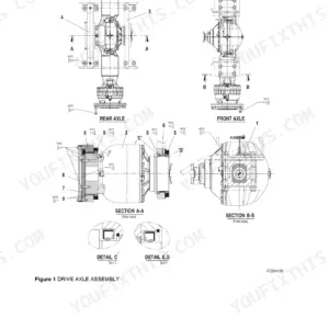
| Axles and Driveshaft | 703-768 | ZF Multitrac MT-L 3115 II / 3125 II Axles, Driveshaft |
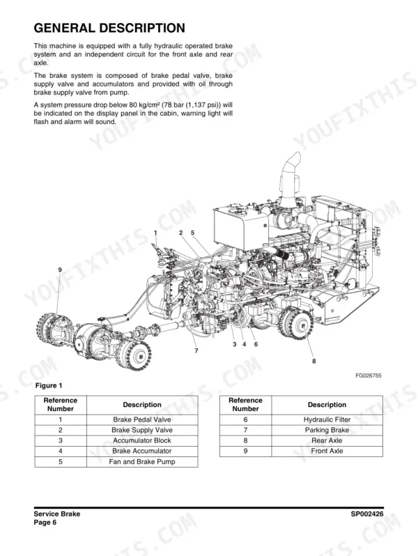
| Brake | 769-824 | Service Brake, Supply Valve, Charging Block, Parking Brake, Brake Pedal Valve, Accumulator |
| Steering | 825-922 | Power Steering System, Steering Unit, Steering Pump, Flow Amplifier, Jerk Softener and Accumulator, Emergency Steering |
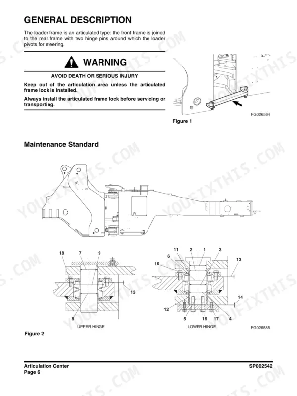
| Frame and Tanks | 923-956 | Articulation Center, Counterweight, Oil Tank, Fuel Tank |
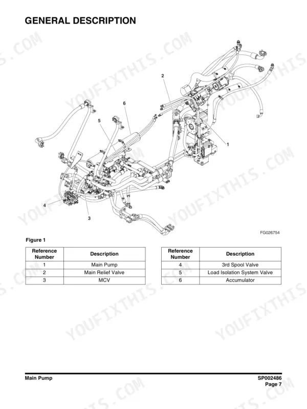
| Hydraulics | 957-1065 | Main Pump, Main Control Valve, 3rd Control Valve (Option), Load Isolation System, Cooling System, Pilot System, Hydraulic Schematic |
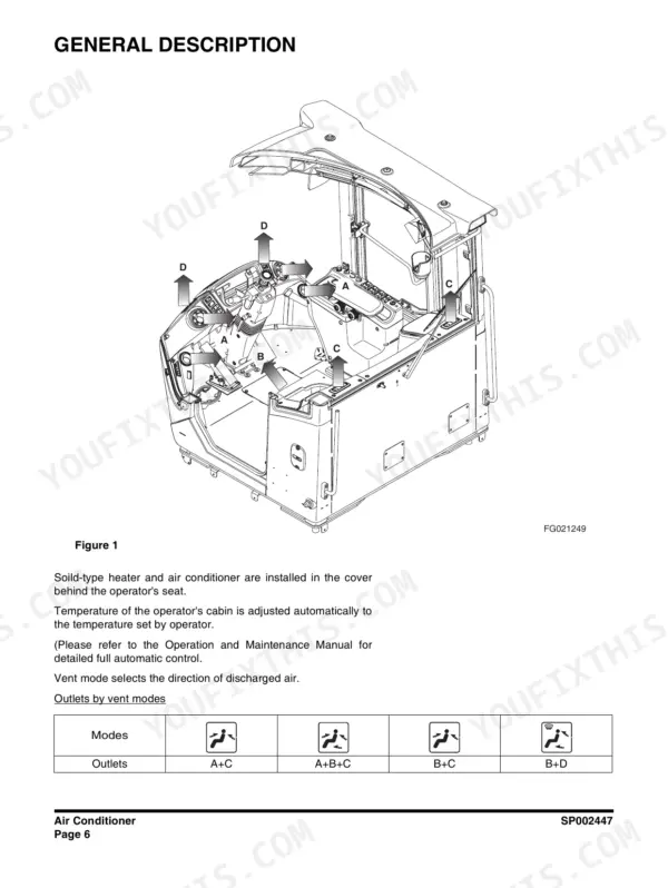
| Electrical System | 1066-1200 | Air Conditioner, Electrical System and Display, Warning Lights, Electrical Schematic |
Quick Reference Specifications
| Specification | Value | Page |
|---|---|---|
| Standard bucket capacity (BOT / BOC) | 5.4 m3 (7.1 yd3) / 5.7 m3 (7.5 yd3) | p. 80 |
| Vehicle weight | 31,540 kg (69,534 lb) | p. 80 |
| Engine maker and model | SCANIA / DC 13 | p. 80 |
| Engine emission | US EPA Tier 4i (EU Stage IIIB) | p. 80 |
| Injection system | Extra high-pressure fuel injection system, XPI | p. 80 |
| Rated gross power | 283 kW (380 HP) @ 1,800 rpm (SAE J1995) | p. 80 |
| Max torque | 178 kg•m / 1,400 rpm (1,287 ft lb @ 1,400 rpm) | p. 83 |
| Transmission | Full Automatic Power Shift, 4 Forward, 3 Reverse (Option 5 Forward, 3 Reverse) | p. 80 |
| Travel brakes | 4 Wheel, Wet Disk | p. 80 |
| Parking brake | SAHR, Dry Disk Type | p. 80 |
| Travel speed, 4 speed | 6.5 (4.0) / 12.4 (7.7) / 19.7 (12.2) / 36 (22.3) km/h (MPH) | p. 80 |
| Steering angle | ±40° | p. 80 |
| Rated operating load | 11,075 kg (24,416 lb) | p. 80 |
| Maximum breakout force (bucket) | 260 kN (58,450 lb) | p. 80 |
| Maximum gradeability | 30° (58%) | p. 80 |
| Wheel base | 3,550 mm (11' 8") | p. 85 |
Doosan DL550-3 Common Problems This Manual Covers
Loader drops into neutral and will not take a gear
ZF code 11 is a logical error at the gear range signal, and the TCU responds by shifting the transmission to neutral. The Transmission Error Codes chapter has you check the cables from the TCU to the shift lever. It also has you check the signal combinations for the F-N-R lever positions.
Manual Section: Transmission Error Codes (ZF) p. 680Vibration or unusual noise from the hydraulics while working the lift arms and bucket
The Hydraulics chapter lists air leaking into the circuit or a defective pump as possible causes. Open the main pump drain plugs and look for grit or metallic particles. Metal in the drain points toward the pump itself, not just an air leak on the suction side.
Manual Section: Hydraulics - Main Pump p. 99Parking brake does not hold well, or new linings have just gone in
The Brake chapter calls for a basic setting of the SAHR parking brake after new lining plates or brake disks are fitted. It is also required during all repair stages and whenever braking performance is insufficient. Do all of the setting work with the brake cold.
Manual Section: Brake - Parking Brake p. 801Buzzer sounds for several seconds after the engine starts
The warning lights section explains that the buzzer sounds for 8 seconds when engine oil pressure drops under 0.7 bar after start. Treat it as a real low oil pressure reading. Then work through the Scania DC13 service procedures in the Engine chapter.
Manual Section: Electrical System - Warning Lights / Engine p. 1125Frequently Asked Questions
The transmission warning light is on and the display shows a code starting with T. Where do I look it up?
The transmission abnormal warning light means the TCU has logged a fault. Read the malfunction entry beginning with T on the display. Then take that code to the ZF fault code table in the Transmission Error Codes chapter. It gives the meaning, the TCU reaction and the possible repair steps for each code. p. 1125
My loader has the 5-speed ZF option. Are its fault codes covered?
Yes. The ZF code table covers both the 4WG four-speed and the 5WG five-speed versions. It applies to ZF software versions V 53.x through V58.0. Check which software your TCU runs before you trust a code reading. p. 680
How do I get air out of the DC13 fuel system?
Fit a clear hose to the bleed nipple on the fuel filter housing. Work the hand pump until fuel runs out of the hose, which takes around 100 strokes. Then start the engine and open the bleed nipple until the fuel comes through free of air. p. 291
Does this manual match my machine?
It is Doosan publication 950106-00434E, dated June 2012, for the DL550-3 wheel loader from serial 10001 and up. The machine it covers runs the Scania DC13 Tier 4i, the ZF 4WG-310 transmission with a 5WG option and ZF Multitrac MT-L 3115 II / 3125 II axles. p. 1
Are the hydraulic and electrical schematics included?
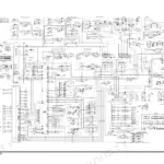
Both are included. The hydraulic schematic sits in the Hydraulics chapter alongside the main pump, the main control valve, the optional 3rd valve, the pilot system and the load isolation system. The electrical schematic is in the Electrical System chapter with the display and warning lights. p. 1065