
Part of the Doosan Repair Manuals.
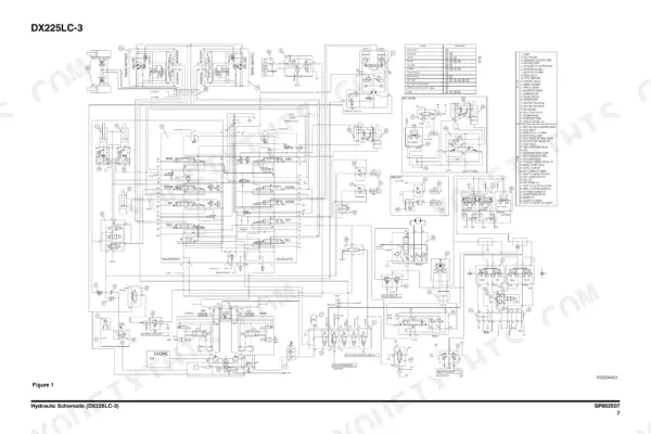
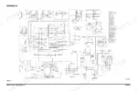
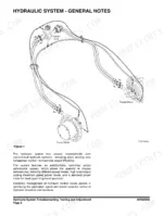
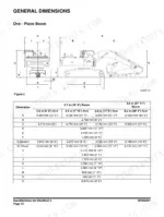
Looking for the Doosan DX225LC-3 service manual PDF straight from the factory? This 874-page shop manual (OEM #950106-00364E) covers the whole DX-3 crawler excavator line: DX140LC-3, DX180LC-3, DX225LC-3, DX255LC-3, and DX300LC-3. Inside you get full hydraulic schematics plus troubleshooting, testing, and adjustment procedures for the main pump, swing device, travel device, and main control valve. Complete electrical schematics trace the starting circuit, charging system, and engine control system wire by wire, and page after page of standard torque tables backs up every job from the swing bearing to the track assembly. Torque your 3/4-inch split flange bolts to 3.0 to 3.7 kg-m (22 to 27 ft lb), then fill the hydraulic system to 240 liters. Your excavator is down and burning money. Grab the download, search any spec by keyword, and get wrenching.
What's Inside This Doosan DX225LC-3 Manual
| System | Pages | Key Topics |
|---|---|---|
| Safety | 5-72 | Track Excavator Maintenance Safety |
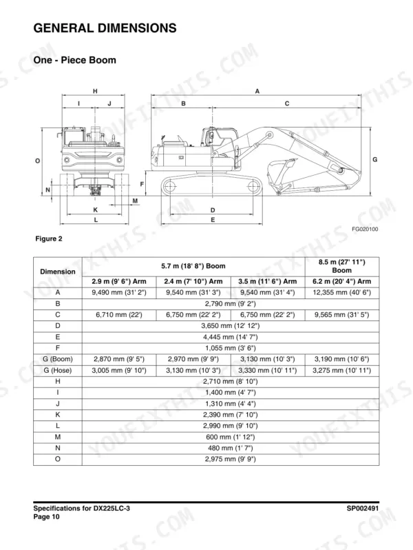
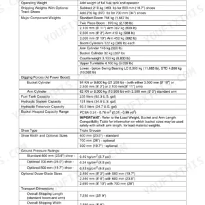
| Specifications | 73-102 | Specifications for DX225LC-3 |
| General Maintenance | 103-140 | Standard Torques |
| Upper Structure | 141-202 | Cabin, Counterweight, Fuel Tank, Fuel Transfer Pump, Swing Bearing |
| Lower Structure and Chassis | 203-236 | Track Assembly |
| Engine and Drivetrain | 237-266 | Engine Coolant Heater, Drive Coupling |
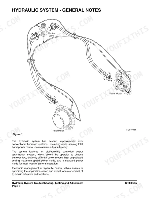
| Hydraulic Troubleshooting, Accumulator and Center Joint | 267-325 | Hydraulic System Troubleshooting, Testing and Adjustment, Accumulator, Center Joint (Swivel) |
| Cylinders, Swing Device and Travel Device | 326-473 | Cylinders, Swing Device, Travel Device, Safety Instructions, General Description, Theory of Operation, Special Tools and Materials |
| Main Pump, PTO Server and Gear Pump | 474-517 | Main Pump, PTO Server, Gear Pump, Safety Instructions, Pump Maintenance, Component Locations, Tools |
| Control Valves and Solenoids | 518-661 | Main Control Valve, Remote Control Valve (Work Lever / Joystick), Travel Control Valve (with Damper), Solenoid Valve Assembly, Breaker EPPR Valve (Option), Safety Instructions, General Description, Theory of Operation, Troubleshooting, Testing and Adjustment |
| Dozer Valve and Hydraulic Schematic | 662-682 | Dozer Valve, Hydraulic Schematic (DX225LC-3), Safety Instructions, Structure Diagram, Performance Specification, Hydraulic Pressure Circuit Diagram |
| Electrical System | 683-848 | Electrical Supply System, Engine Starting Circuit, Charging System, Monitoring System, Engine Control System, Air Conditioner System |
| Attachments | 849-874 | Boom and Arm, Bucket |
Quick Reference Specifications
| Specification | Value | Page |
|---|---|---|
| Split Flange 1/2" Bolt Torque | 2.1 - 2.5 kg•m (15 - 18 ft lb) | p. 135 |
| Split Flange 3/4" Bolt Torque | 3.0 - 3.7 kg•m (22 - 27 ft lb) | p. 135 |
| Replacement Period | 1,000 hr | p. 719 |
| Fuel Tank Capacity | 400 liters | p. 90 |
| Hydraulic System Capacity | 240 liters | p. 90 |
| Hydraulic Reservoir Capacity | 200 liters | p. 90 |
| Main Relief Pressure (Normal) | 330 kg/cm2 | p. 96 |
| Main Relief Pressure (Pressure Up) | 350 kg/cm2 | p. 96 |
| Travel Control Valve Pressure/Stroke | 25 kg/cm2 @ 4.3 mm | p. 620 |
| Travel Device Gear Oil Quantity | 3.3 liters | p. 432 |
| Breaker EPPR Valve Bolt Torque (M35) | 450 ± 50 kg•cm | p. 656 |
| Main Control Valve Relief Valve Torque | 7.95 - 8.97 kg•m | p. 577 |
Doosan DX225LC-3 Common Problems This Manual Covers
Doosan DX225LC-3 hydraulic functions sluggish and weak, boom slow under load, dig power fading
Check the hydraulic reservoir level first; the tank holds 200 liters and the full system takes 240 liters, per the specs on page 90. Test main relief pressure at the pump: 330 kg/cm2 normal, 350 kg/cm2 in pressure-up mode (page 96). Replace the pilot filter if it has more than 1,000 hours on it.
Manual Section: Hydraulic System Troubleshooting, Testing and Adjustment p. 267Hydraulic oil temperature climbs into the red during normal digging, functions get spongy when hot
Verify oil level in the reservoir before anything else; a low charge in the 240 liter system overheats fast. Clean the oil cooler fins and dust net with compressed air. If temperature still climbs, test the main relief valve against the 330 kg/cm2 spec on page 96; a stuck relief dumps heat into the oil constantly.
Manual Section: Hydraulic Problems TroubleshootingEngine cranks slowly or will not fire on cold mornings after sitting overnight
Test battery voltage under load and clean the ground straps before condemning the starter. Drain the water separator, replace the fuel prefilter element, and prime the system. Verify fuel level; the tank holds 400 liters and pickup trouble shows up when it runs low. Then work through the engine starting circuit tests beginning on page 683.
Manual Section: Electrical System p. 683Travel motor whines and runs hot on one side, machine pulls left when tracking
Drain the travel device gear oil and check for metal flake; each final drive takes 3.3 liters on refill, per page 432. Compare travel spool pilot pressure side to side; the travel control valve should build 25 kg/cm2 at 4.3 mm of stroke. Uneven readings point at the pilot circuit, not the motor.
Manual Section: Travel Device Troubleshooting p. 432Tracks keep derailing and rollers wearing fast, undercarriage clatters on every pass across the pad
Measure roller and idler bushing wear before throwing parts at it. Standard shaft-to-bushing clearance is 0.40 to 0.48 mm on lower rollers (page 216) and 0.430 to 0.505 mm on the front idler (page 218). Clearance well past those numbers lets the roller wobble enough to walk the track off. Replace worn rollers in pairs.
Manual Section: Lower Structure and Chassis p. 216Boom and bucket pins knocking, sloppy attachment movement even with cylinders holding pressure fine
Check pin-to-bushing clearance with a dial indicator at each joint. Boom foot standard clearance is 0.13 to 0.33 mm with a 1.5 mm wear limit; arm link and bucket rod joints run 0.09 to 0.29 mm with a 2.0 mm limit, all listed on page 857. Replace any pin and bushing past its limit as a set.
Manual Section: Attachments p. 857Frequently Asked Questions
How do I clear the maintenance light on a Doosan DX225LC-3?
To reset the operation hour or change the replacement period for filters and oil, use the 'Filter/Oil Information' screen under the 'Vehicle State' menu. Turn the jog switch to locate the cursor, click to select the item, and then choose 'YES' to reset the operation hour. p. 134
What is the fuel tank capacity for the DX225LC-3?
The fuel tank capacity for the DX225LC-3 is 400 liters (106 U.S. gal). p. 90
What is the correct torque for the main relief valve on the DX225LC-3?
The main relief valve on the DX225LC-3 should be tightened to a torque of 7.95 - 8.97 kg•m (58 - 65 ft lb). p. 139
How often should the gear oil in the travel device be changed?
The first gear oil change for the travel device should be performed after 500 operating hours, and subsequent changes should occur every 1000 operating hours or once a year. p. 140
Do I get instant access to this Doosan DX225LC-3 Service Manual?
Delivery is instant: a 874-page searchable PDF is yours the second checkout clears. Laptop, tablet, or phone, all fine.
Can I print a copy of this Doosan DX225LC-3 Service Manual for the shop?
Yes. Print a single page or a chapter for your own shop use, on letter or A4.
Is there a wiring diagram in this Doosan DX225LC-3 Service Manual?
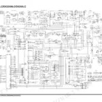
Included, and complete: electrical schematics, wire routing, connector pinouts, and circuit descriptions for the Doosan DX225LC-3. There is one on page 113, for example.






Reviews
There are no reviews yet.