
Part of the Doosan Repair Manuals.
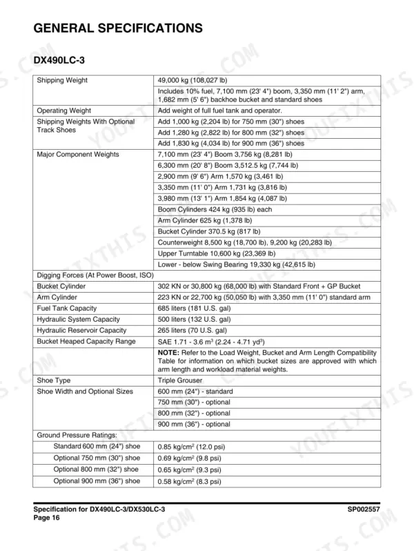
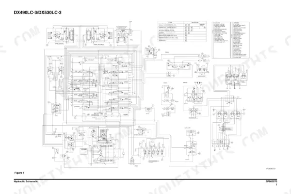
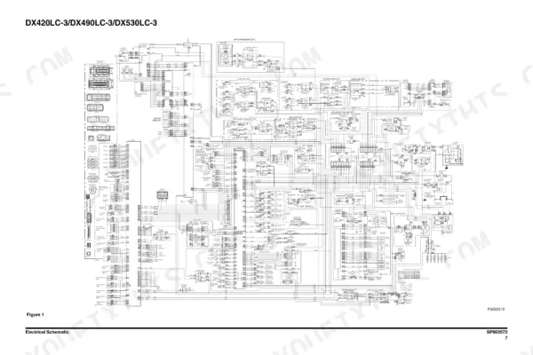
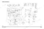
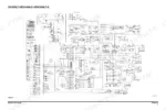
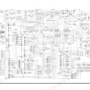
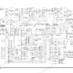
This is the factory shop manual for the Doosan DX490LC-3 and DX530LC-3 crawler excavators, 2012 edition (publication 950106-00259E, printed May 2012). It covers the whole machine: the Isuzu 6WG1 common-rail diesel with full disassembly, DTC diagnostics and wiring, the A8VO200 main pump, main control valve, swing and travel devices, cylinders, undercarriage, cab and counterweight removal, plus attachments. The complete ISO hydraulic schematic (SP002570) and full machine electrical schematic (SP002572) are bound in, so you are not chasing a separate schematic book for most work. Specs are real numbers: 394.28 ps at 1,800 rpm, 330 kg/cm2 main relief (350 with Pressure Up), 500 liter hydraulic system. If you keep one of these 49 to 52 ton machines digging, this is the book the dealer techs use.
What's Inside This Doosan DX490LC-3, DX530LC-3 Manual
| System | Pages | Key Topics |
|---|---|---|
| Safety | 5-72 | Maintenance Safety, Fire and Explosion Prevention, Personal Protective Equipment, Emergency Procedures |
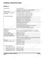
| Specifications | 73-104 | Model Identification, Serial Number Ranges, Operating Dimensions, ROPS Certification |
| General Maintenance | 105-142 | Maintenance Instructions, Standard Torques, Cleaning Procedures, Long-Term Storage |
| Upper Structure | 143-204 | Cabin, Counterweight, Fuel Tank, Swing Bearing |
| Lower Structure and Chassis | 205-238 | Track Assembly, Undercarriage Maintenance |
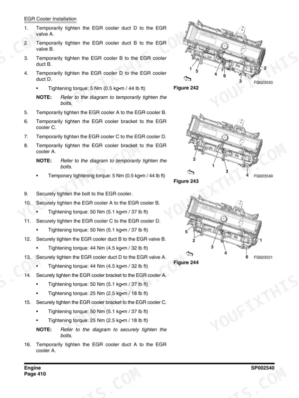
| Engine - Service Information and Maintenance | 239-341 | Engine Service Information Guide, Maintenance Information, Plastic Gauge Use, Special Tools, Abbreviations |
| Engine - Functional Inspection, Symptom and DTC Diagnostics | 342-452 | Functional Inspection, Engine Compression Pressure Inspection, Fuel System Check, Air Intake System Check, Exhaust System Check, DPD Control System Check |
| Engine - Engine Control System | 453-598 | Engine Control, DTC P-Code Diagnostics with Flash Codes, ECM Programming, Sensor and Injector Circuit Tests |
| Engine - Mechanical Disassembly and Assembly | 599-1032 | Mechanical, Cylinder Head Cover, Cylinder Head Assembly, Idle Gear, Cylinder Block, Crankshaft |
| Engine - Fuel, Cooling and Lubrication Systems | 1033-1180 | Fuel System, Fuel Supply Pump, Injector, Fuel Filter, Pressure Limiter, Fuel Pressure Sensor |
| Engine - Induction, Exhaust and Emission Control | 1181-1235 | Induction, Boost Temperature Sensor, Turbocharger Assembly, Intercooler, Air Cleaner Filter, IMT Sensor |
| Engine - Electrical and Wiring Diagram | 1236-1304 | Electrical, Glow Plug, Starter Assembly, Supplementary Information, Wiring Diagram, Using the Wiring Diagram |
| Engine Coolant Heater and Drive Coupling | 1305-1330 | Engine Coolant Heater (Option), Disassembly and Assembly, Changing the Circulating Pump, Changing the Temperature Limiter, Changing the Temperature Sensor, Changing the Combustion Air Fan |
| Hydraulic System Troubleshooting, Testing and Adjustment | 1331-1390 | Hydraulic System Troubleshooting, Testing and Adjustment, Hydraulic System - General Notes, Hydraulic Schematic, General Notes, Operation of Working Components, Boom Operating Circuit |
| Cylinders, Swing Device and Travel Device | 1391-1532 | Cylinders, General Description, Theory of Operation, Parts List, Special Tools and Materials, Piston Nut |
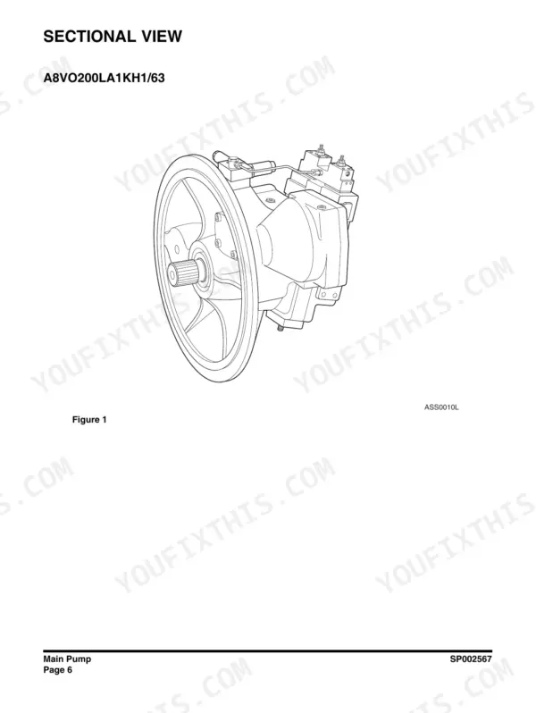
| Main Pump and Gear Pump | 1533-1600 | Main Pump A8VO200LA1KH1/63, Sectional View, Seal Kits, Driveshaft and Control Housing Service, Gear Pump |
| Main Control Valve | 1601-1658 | General Description, When All Spools Are in Neutral, Single Operation, Combined Operation, Antidrift Valve |
| Fan Motors and Fan Pump | 1659-1718 | Fan Motor for Oil Cooler, Disassembly, Assembly, Preassemble, Assembling, Fan Motor for Radiator |
| Remote, Travel, Solenoid and Breaker EPPR Valves | 1719-1792 | Remote Control Valve (Work Lever / Joystick), General Description, Theory of Operation, Parts List, Specifications, Torques |
| Hydraulic Schematic | 1793-1802 | DX490LC-3/DX530LC-3 |
| Electrical System | 1803-1956 | Electrical Schematic, Battery Maintenance, Boost Starting, Electrical Shock Prevention |
| Electrical Schematic | 1957-1966 | DX420LC-3/DX490LC-3/DX530LC-3 |
| Attachments | 1967-1992 | Boom and Arm, Bucket, Work Tool Compatibility |
Quick Reference Specifications
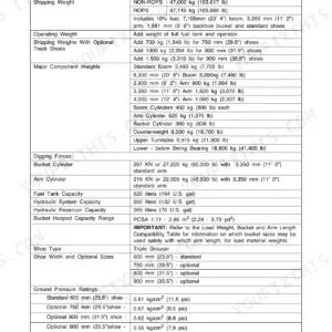
| Specification | Value | Page |
|---|---|---|
| Engine model | Isuzu 6WG1, diesel 4-cycle water-cooled inline 6-cylinder OHC | p. 269 |
| Engine power (rated) | 394.28 ps (389 hp) @ 1,800 rpm | p. 95 |
| Engine maximum torque | 197.82 kg·m (1,430 ft lb) @ 1,350 rpm | p. 95 |
| Main relief pressure | 330 kg/cm² (4,693 psi); 350 kg/cm² (4,978 psi) with Pressure Up | p. 98 |
| Pilot pressure that opens the control spools | 7 - 9 kg/cm² (100 - 130 psi) | p. 1343 |
| Hydraulic system capacity | 500 liters (132 U.S. gal) | p. 90 |
| Hydraulic reservoir capacity | 265 liters (70 U.S. gal) | p. 90 |
| Shipping weight, DX490LC-3 | 49,000 kg (108,027 lb) | p. 90 |
| Shipping weight, DX530LC-3 | 51,800 kg (114,200 lb) | p. 92 |
| Bucket digging force, DX490LC-3 | 302 kN or 30,800 kg (68,000 lb) | p. 90 |
| Arm digging force, DX490LC-3 | 223 kN or 22,700 kg (50,050 lb) | p. 90 |
| Bucket digging force, DX530LC-3 | 295 kN or 30,063 kg (66,280 lb) | p. 92 |
| Arm digging force, DX530LC-3 | 253 kN or 25,789 kg (56,855 lb) | p. 92 |
| Ground pressure on 600 mm (24") shoe | 0.85 kg/cm² (12.0 psi) DX490LC-3; 0.89 kg/cm² (12.7 psi) DX530LC-3 | p. 90 |
| Track shoe widths | 600 mm (24") standard; 750 mm (30"), 800 mm (32"), 900 mm (36") optional | p. 90 |
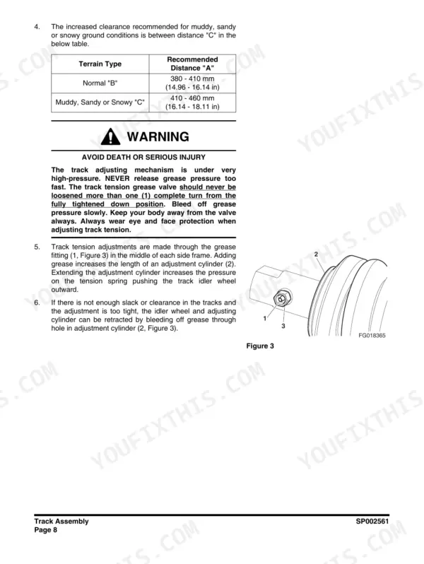
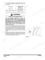
| Track tension, recommended distance "A" | 380 - 410 mm (14.96 - 16.14 in) normal ground; 410 - 460 mm (16.14 - 18.11 in) muddy, sandy or snowy | p. 214 |
| Track adjuster grease valve | never loosen more than one full turn from fully tightened; 27 mm socket | p. 214 |
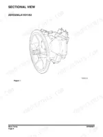
| Main pump | Rexroth A8VO200LA1KH1/63 | p. 1538 |
| Alternator | 24V x 80A | p. 95 |
| Counterweight | 8,500 kg (18,700 lb) or 9,200 kg (20,283 lb) | p. 90 |
Doosan DX490LC-3, DX530LC-3 Common Problems This Manual Covers
Track runs loose, sags badly, or throws itself off the frame in a turn.
Measure sag against the spec and add grease at the mid-frame fitting per the track tension procedure on page 214. If tension will not hold, measure link pins and bushings for wear against the limits in Lower Structure and Chassis before buying track.
Manual Section: Lower Structure and Chassis - Undercarriage Maintenance p. 214Track adjusted too tight, loading rollers, idlers and the final drive hard.
Bleed grease at the adjuster valve using a 27 mm socket, opening it no more than one full turn as the manual warns, then recheck sag. The Lower Structure and Chassis section explains the adjuster cylinder so you know what that valve is holding back.
Manual Section: Lower Structure and Chassis - Track Assembly p. 214Rollers, idlers, pins and bushings wearing out faster than the hours justify.
Usually wrong tension for the ground conditions: mud and sand pack the chain and need a looser setting. The undercarriage maintenance coverage in Lower Structure and Chassis gives the sag ranges, and General Maintenance covers cleaning routines that keep abrasive pack-out from grinding the chain.
Manual Section: General Maintenance - Cleaning Procedures p. 217Idler or track assembly rebuilt, then fails again shortly after the repair.
Common cause is skipping the oil refill or seal detail on reassembly. Follow the Track Assembly disassembly and assembly steps in Lower Structure and Chassis, refill the idler with the specified gear oil, and set tension to spec before releasing the machine.
Manual Section: Lower Structure and Chassis - Track Assembly p. 222Frequently Asked Questions
How do I clear error codes on a DX490LC-3 or DX530LC-3?
Machine fault codes show on the gauge panel in the V-number format, for example V000264 with an FMI number. The gauge panel menu has a Delete Failure Log function, covered on page 1890, and a Reset Operation Hour item in the same menu area. Fix the fault first, because an active failure comes right back after you delete the log. Engine codes stored in the Isuzu ECM are a separate list and are worked through the engine diagnostic procedures in the book, not the panel log. p. 1890
What do the engine fault codes mean, like P0087 or P0088?
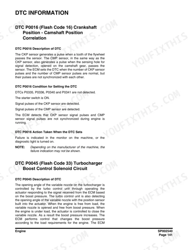
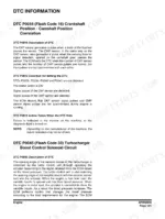
Engine codes print as standard P-codes with an Isuzu flash code alongside. Examples straight from the book: DTC P0016 (Flash Code 16) is crankshaft to camshaft position correlation, P0087 (Flash Code 225) is fuel rail pressure too low, P0088 (Flash Code 118) is rail pressure too high, P0089 (Flash Code 151) is fuel pressure regulator performance. Each code gets its own step-by-step diagnostic in the Engine Control System section, and there is an SPN-FMI to P-code mapping table around pages 450-452 if your reader shows J1939 numbers. p. 450
How do I adjust track tension on these machines?
There is a grease fitting in the middle of each track side frame. Pump grease in to tighten the track, and to loosen it crack the grease valve open with a 27 mm socket, no more than one full turn, and let grease bleed out. That one-turn limit matters: the adjuster is under real pressure and backing the valve out too far is how people get hurt. The procedure with the sag spec is on page 214 in the undercarriage maintenance coverage. p. 214
Does the manual have torque specs for track shoe bolts and other hardware?
Yes. The General Maintenance section carries the standard torque charts by bolt size and grade, and the component sections list specific tightening torques where a fastener needs its own value, such as the cylinder piston nut coverage and the remote control valve torque tables. That is where you look before reusing a value from memory, because a track shoe bolt on a 49,000 kg machine is not the place to guess. p. 127
Are both models covered, and how deep does the engine coverage go?
One book covers the DX490LC-3 and DX530LC-3, with separate spec pages where they differ, such as shipping weight at 49,000 kg for the DX490LC-3 and 51,800 kg for the DX530LC-3. The engine coverage is the full Isuzu 6WG1 service manual bound into the book, over a thousand pages: compression testing, DTC diagnostics, injector and supply pump work, turbocharger, DPD checks, cylinder head and crankshaft disassembly, and engine wiring diagrams. p. 269






Reviews
There are no reviews yet.