
Part of the Doosan Repair Manuals.
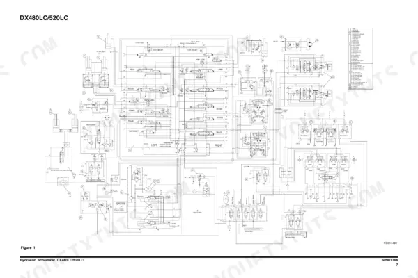
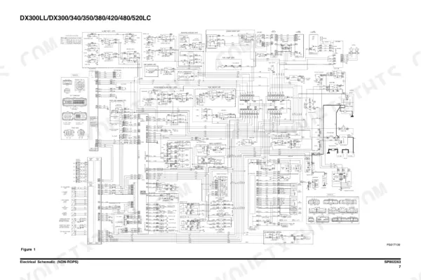
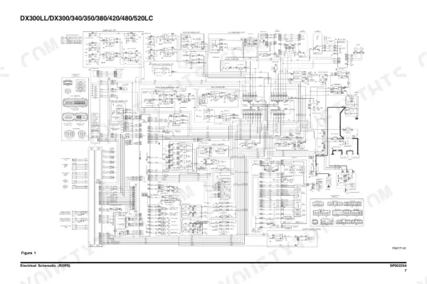
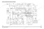
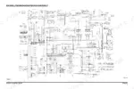
This is the factory shop manual Doosan issued for the DX480LC and DX520LC crawler excavators, publication K1008703CE, 2010 edition, covering the DV11-powered K-series machines. Inside you get cab removal and installation for both NON-ROPS and ROPS versions, track assembly wear limits and tension procedure, main pump drive coupling install, and full teardown coverage of the hydraulics: main pump (A8VO200), main control valve, swing motor, travel motor with gearbox, center joint, all three cylinder types, fan drive gear pump, vane fan motor, joystick remote control valves, and the solenoid valve block. The complete hydraulic schematic sits on page 729, and separate NON-ROPS and ROPS electrical schematics are printed at pages 970 and 977. Testing and adjustment specs included.
Other editions of this manual
What's Inside This Doosan DX480LC, DX520LC Manual
| System | Pages | Key Topics |
|---|---|---|
| Safety | 7-52 | Track Excavator Safety, Safety Precautions, To the Operator of a DOOSAN Excavator, Learn Signal Words Used with Safety Alert Symbol, General Safety Essentials, Accessory Applications |
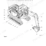
| Specifications | 53-88 | Specification for DX480LC/520LC, Safety Precautions, General Description, Component Locations, General Dimensions (DX480LC), General Dimensions (DX520LC) |
| General Maintenance | 89-126 | General Maintenance Procedures, Safety Precautions, Welding Precautions and Guidelines, Hydraulic System - General Precautions, Maintenance Service and Repair Procedure, General Precautions |
| Upper Structure | 127-258 | Cabin (Non-ROPS), Safety Precautions, Cab Identification, Removal, Installation, Cabin (ROPS) |
| Lower Structure and Chassis | 259-298 | Track Assembly, Safety Precautions, General Description, Track Tension, Cleaning and Inspection (Wear Limits and Tolerances), Track Shoe |
| Engine and Drive Train | 299-308 | Drive Coupling (Main Pump), Safety Precautions, Drive Coupling, Installation of Drive Coupling, Installation Procedure |
| Hydraulics - Hydraulic System Troubleshooting, Testing and Adjustment | 309-344 | Hydraulic System Troubleshooting, Testing and Adjustment, Safety Precautions, Hydraulic System - General Notes, Hydraulic Schematic, General Notes, Operation of Working Components |
| Hydraulics - Accumulator to Cylinders | 345-382 | Accumulator, Safety Precautions, General Description, Specifications, Center Joint (Swivel), Center Joint Disassembly Diagram |
| Hydraulics - Swing Motor | 383-418 | Swing Motor, Safety Precautions, Operation Manual, Information on Marking, Specifications, Structure and Operational Principles |
| Hydraulics - Travel Motor (with Gearbox) | 419-482 | Travel Motor (with Gearbox), Safety Precautions, General Description, Theory of Operation, Hydraulic Motor Operation, Reduction Gearbox Operation |
| Hydraulics - Main Pump | 483-540 | Main Pump, Safety Precautions, Ectional View, A8VO200LA1KH1/63, General Repair Guidelines, Seal Kits and Sub- Assemblies |
| Hydraulics - Gear Pump (Fan Cooling Drive) | 541-558 | Gear Pump (Fan Cooling Drive), Safety Precautions, Disassembling Single Gear Pump, Reassembling Single Gear Pump, Disassembling Double Gear Pump(Opt), Reassembling Double Gear Pump(Opt) |
| Hydraulics - Main Control Valve | 559-616 | Main Control Valve, Safety Precautions, General Description, When All Spools Are in Neutral, Single Operation, Combined Operation |
| Hydraulics - Remote Control Valve (Work Lever / Joystick) | 617-638 | Remote Control Valve (Work Lever / Joystick), Safety Precautions, General Description, Structure, Function, Parts List |
| Hydraulics - Travel Control Valve (with Damper) | 639-664 | Travel Control Valve (with Damper), Safety Precautions, General Description, Theory of Operation, Pressure Reducing Valve, Operating Theory of Damper Mechanism |
| Hydraulics - Fan Motor (Vane Type) | 665-686 | Fan Motor (Vane Type), Safety Precautions, Parts List, Introduction and Description, Description, Applications |
| Hydraulics - Fan Cooling Flow In-Out Change Valve and Solenoid Valve Assembly | 687-710 | Fan Cooling Flow In-Out Change Valve, Safety Precautions, Cooling Fan a Change of Direction Valve, Solenoid Valve Assembly, 5-Solenoid Valve, Parts List |
| Hydraulics - Breaker EPPR Valve (Opt) and Hydraulic Schematic DX480LC/520LC | 711-729 | Breaker EPPR Valve (Opt), Safety Precautions, Structure, Numbers and Names of Parts, Functions and Operation, Cautions for Operation |
| Electrical System - Electrical System (Non-ROPS) | 730-847 | Electrical System (Non-ROPS), Safety Precautions, Electrical Supply System, Engine Starting Circuit, Start Operation, After Start |
| Electrical System - Electrical System (ROPS) | 848-963 | Electrical System (ROPS), Safety Precautions, Electrical Supply System, Engine Starting Circuit, Start Operation, After Start |
| Electrical System - Electrical Schematic (Non-ROPS) and Electrical Schematic (ROPS) | 964-977 | Electrical Schematic (Non-ROPS), Safety Precautions, DX300LL/DX300/340/350/380/420/480/520LC, Electrical Schematic (ROPS) |
| Attachments | 978-1007 | Boom and Arm, Safety Precautions, Front Attachment Pin Specifications, DX300LC, DX340LC / DX350LC, DX420LC |
Quick Reference Specifications
| Specification | Value | Page |
|---|---|---|
| Engine model | DV11, performance rated to DIN 6270 | p. 77 |
| Alternator | 24V x 50A | p. 77 |
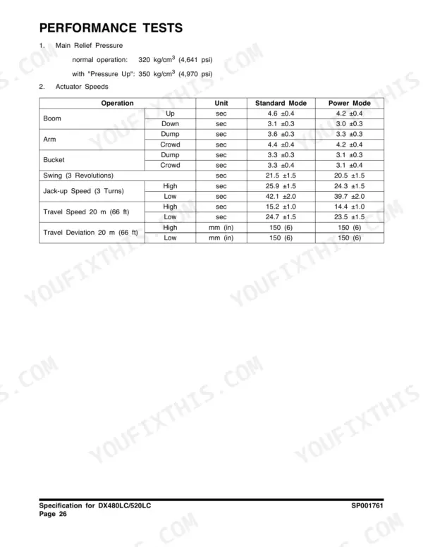
| Main relief pressure | 320 kg/cm² (4,641 psi); 350 kg/cm² (4,970 psi) with Pressure Up | p. 80 |
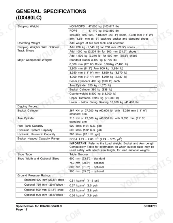
| Shipping weight, DX480LC | 47,000 kg (103,617 lb) | p. 72 |
| Shipping weight, DX520LC | 47,110 kg (103,860 lb) | p. 74 |
| Bucket digging force | 267 kN or 27,200 kg (60,000 lb) | p. 72 |
| Arm digging force | 216 kN or 22,000 kg (48,500 lb) with 3,350 mm (11' 0") arm | p. 72 |
| Fuel tank capacity | 620 liters (164 U.S. gal) | p. 72 |
| Hydraulic system capacity | 500 liters (132 U.S. gal) | p. 72 |
| Hydraulic reservoir capacity | 265 liters (70 U.S. gal) | p. 72 |
| Counterweight | 8,500 kg (18,700 lb) | p. 72 |
| Upper turntable weight | 9,915 kg (21,900 lb) | p. 72 |
| Lower structure weight, below swing bearing | 18,800 kg (41,400 lb) | p. 72 |
| Standard boom weight | 3,490 kg (7,700 lb) | p. 72 |
| Arm weight, 3,350 mm | 1,620 kg (3,570 lb) | p. 72 |
| Ground pressure, 600 mm (23.6") shoe | 0.81 kg/cm² (11.5 psi) | p. 72 |
| Ground pressure, 750 mm (29.5") shoe | 0.67 kg/cm² (9.5 psi) | p. 72 |
| Optional shoe weight penalty | add 700 kg (1,540 lb) for 750 mm; 1,500 kg (3,310 lb) for 900 mm | p. 72 |
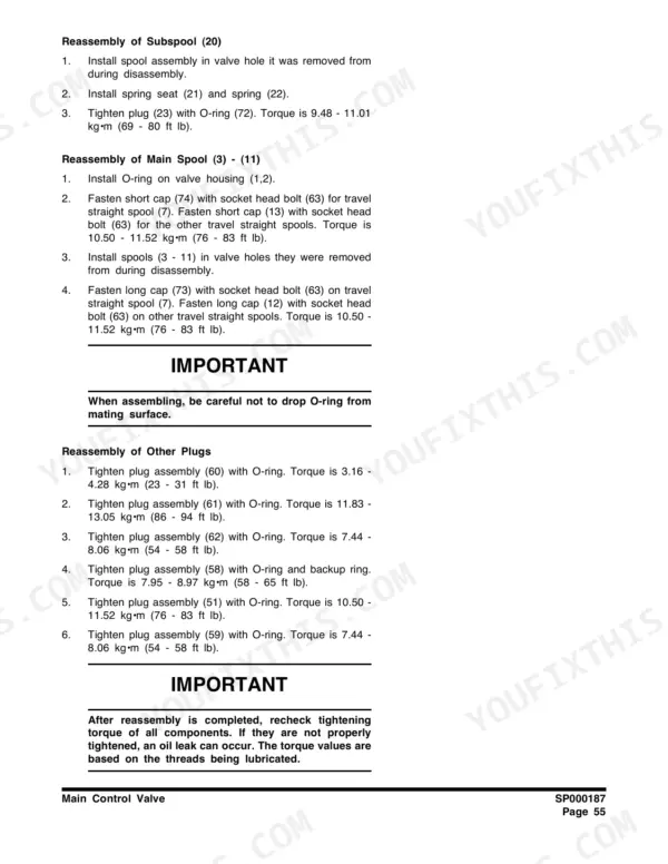
| Main control valve subspool plug torque | 9.48 - 11.01 kg·m (69 - 80 ft lb) | p. 613 |
| Main control valve cap bolt torque | 10.50 - 11.52 kg·m (76 - 83 ft lb) | p. 613 |
Doosan DX480LC, DX520LC Common Problems This Manual Covers
Weak digging force, slow cycles, abnormal pump noise, or hydraulic oil running hot
Start with the Hydraulic System Troubleshooting, Testing and Adjustment chapter: hook up gauges, verify the 320 kg/cm² main relief against the page 80 spec, check for air in the suction side, and pull the return filter looking for metallic particles before condemning the pump.
Manual Section: Hydraulics - Hydraulic System Troubleshooting, Testing and Adjustment p. 309Machine loses travel, tracks one side, or moves jerky under load
The Travel Motor (With Gearbox) chapter covers hydraulic motor theory, reduction gearbox operation, and inspection of the gears and seals that wear out first. Follow its disassembly sequence and inspect for lubrication breakdown and contamination before ordering a complete motor.
Manual Section: Hydraulics - Travel Motor (With Gearbox) p. 419Noisy swing, loss of swing power, or the house drifts on a slope
Work through the Swing Motor chapter, which gives the structure, operational principles, and specifications for teardown. Check for internal leakage, scored rotating group parts, and damaged seals and O-rings. Contamination during reassembly kills these units, so follow the cleanliness notes exactly.
Manual Section: Hydraulics - Swing Motor p. 383Oil leaking at the center of the undercarriage, or travel functions acting up together
That points at the swivel. The Center Joint chapter includes the disassembly diagram, seal locations, and reassembly procedure. Leakage here usually means worn internal seals or contamination in the joint; the section walks a full overhaul so you replace every O-ring in one pass.
Manual Section: Hydraulics - Center Joint (Swivel) p. 353Frequently Asked Questions
What does error code E11 or E13 mean on a DX480LC/DX520LC?
First thing: on these 2010 K-series machines the gauge panel shows codes in the E011 style, plus V-codes like V201, V202, V204, and V228 through V232. If you are seeing P-codes, flash codes, or six-digit codes, you are reading the wrong generation of Doosan book. This manual covers the gauge panel and electrical system for both cab versions, and the full electrical schematics on pages 970 and 977 are what you actually use to chase a code back to a sensor or harness fault. One trap to avoid: the numbered warning lamps on the panel, like the water-in-fuel lamp, are indicator lights, not fault codes. Do not mix the two lists up. p. 970
How do I reset the monitor or clear codes on this machine?
There is no magic button trick worth chasing. On this generation, a code stays because the fault is still live. The honest path is the one this manual lays out: use the Electrical System sections (NON-ROPS or ROPS, whichever cab you have) to understand the supply and starting circuits, then trace the flagged circuit on the schematic sheets at pages 970 and 977. Fix the sensor, connector, or wire, and the panel stops complaining. I have seen plenty of guys swap parts at random trying to make a code go away; twenty minutes with the schematic and a meter is cheaper. p. 730
Does it have torque specs for the hydraulic components?
Yes, in the component chapters where you need them. For example, the Main Control Valve section gives the subspool plug torque at 9.48 to 11.01 kg·m (69 to 80 ft lb) and the cap bolts at 10.50 to 11.52 kg·m (76 to 83 ft lb), on page 613. The swing motor, travel motor, main pump, and cylinder sections each carry their own reassembly torque tables and seal kit breakdowns. If you are rebuilding a slew motor without these numbers you are guessing, and guessed torque on a valve cap is how you get a weep that never stops. p. 613
Is the full hydraulic schematic included, with relief pressures?
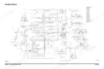
Yes. The complete DX480LC/520LC hydraulic schematic is printed on page 729 (SP001766), and the Hydraulic System Troubleshooting, Testing and Adjustment chapter tells you where to tap gauges and what you should read. Main relief is 320 kg/cm² (4,641 psi), rising to 350 kg/cm² (4,970 psi) with Pressure Up active, spec'd on page 80. That chapter is the one I would open first on any weak-dig or slow-cycle complaint, before touching a wrench. p. 729
Which machines does this book actually cover?
DX480LC and DX520LC only, the 2010 edition. Shipping weights are 47,000 kg for the 480 and 47,110 kg for the 520, so these are the big brothers of the K-series line. One note so you do not get confused: the electrical schematic sheet inside lists a pile of other models (DX300, DX340, and so on) because Doosan printed one shared sheet across the family. That does not mean the mechanical chapters apply to those machines. If you run a smaller DX, get the book for that model. p. 72






Reviews
There are no reviews yet.