
Part of the Doosan Repair Manuals.
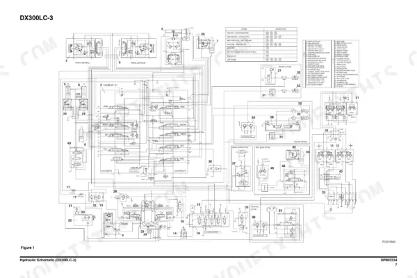
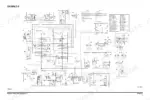
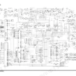
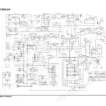
Looking for the Doosan DX300LC-3 shop manual PDF straight from the factory? All 888 pages of this Shop Manual (OEM #950106-00215E) cover the DX300LC-3 excavator from swing bearing to track assembly. Inside: full hydraulic schematics, electrical wiring diagrams for the starting, charging, and monitoring circuits, and a complete troubleshooting section for pilot pressure, power mode valve, and pump input power control. You also get step-by-step disassembly and reassembly procedures for the main pump, swing device, travel motor, and boom and arm cylinders. Set main relief at 350 kg/cm2 (370 in pressure-up mode) and fill the hydraulic system to 280 liters total. No more chasing hydraulic faults on a 30-ton machine with borrowed numbers. Bookmarked and keyword-searchable; download it, pull it up on your tablet next to the machine, and get to work.
What's Inside This Doosan DX300LC-3 Manual
| System | Pages | Key Topics |
|---|---|---|
| Safety | 5-72 | Track Excavator Maintenance Safety |
| Specifications | 73-102 | Specifications for DX300LC-3 |
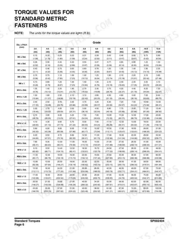
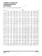
| General Maintenance | 103-140 | Standard Torques |
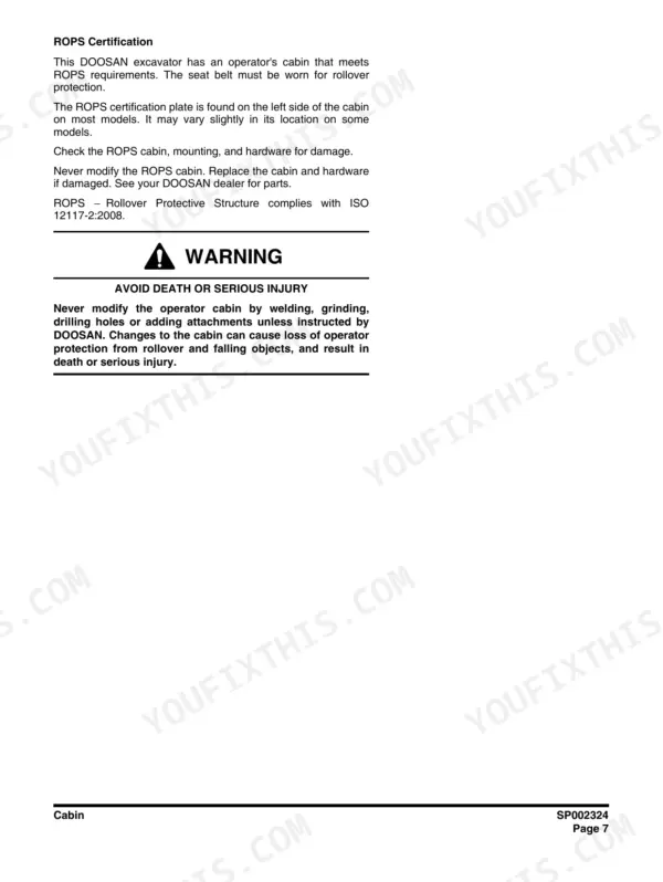
| Upper Structure | 141-202 | Cabin, Counterweight, Fuel Tank, Fuel Transfer Pump, Swing Bearing |
| Lower Structure and Chassis | 203-236 | Track Assembly |
| Engine and Drivetrain | 237-266 | Diesel Heater, Drive Coupling |
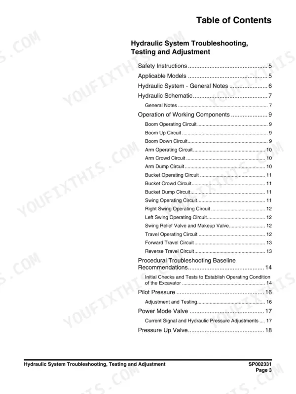
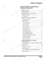
| Hydraulic System Troubleshooting, Testing and Adjustment | 267-302 | Troubleshooting, Pilot Pressure, Power Mode Valve, Pressure Up Valve, Pump Input Power Control |
| Accumulator | 303-310 | Gas-Charged Storage, Precharge Pressure, Specifications, Maintenance |
| Center Joint (Swivel) | 311-324 | Swivel Joint, Inspection, Disassembly, Reassembly, Leakage Prevention |
| Cylinders | 325-364 | Boom Cylinder, Arm Cylinder, Piston Nut, Slipper Seal, Disassembly, Reassembly |
| Swing Device | 365-416 | Swing Motor, Reduction Gear, Reactionless Valve, Brake Part, Disassembly, Reassembly |
| Travel Device | 417-476 | Travel Motor, Reduction Gear, Brake Valve, High-Low Speed Switching, Disassembly, Reassembly |
| Main Pump | 477-522 | Axial Piston Pump, Regulator, Flow Control, Horsepower Control, Disassembly, Reassembly |
| Gear Pump (Option) / Main Control Valve / Breaker EPPR Valve (Option) / Hydraulic Schematic | 523-694 | Gear Pump, Main Control Valve, Breaker EPPR Valve, Hydraulic Schematic, Troubleshooting |
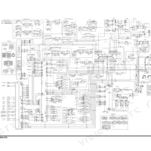
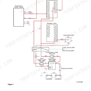
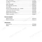
| Electrical System | 695-860 | Electrical Supply System, Engine Starting Circuit, Engine Preheating System, Charging System, Monitoring System, Air Conditioner System |
| Attachments | 861-888 | Boom and Arm, Bucket |
Quick Reference Specifications
| Specification | Value | Page |
|---|---|---|
| Main Relief Pressure (Normal) | 350 kg/cm² | p. 96 |
| Main Relief Pressure (Pressure Up) | 370 kg/cm² | p. 96 |
| Fuel Tank Capacity | 500 liters | p. 90 |
| Hydraulic System Capacity | 280 liters | p. 90 |
| Hydraulic Reservoir Capacity | 165 liters | p. 90 |
| Engine Power | 216 ps | p. 93 |
| Max Torque | 99 kg•m | p. 93 |
| Fuel Consumption (Rated) | 160 g/ps•h | p. 93 |
| Counterweight Weight | 5,300 kg | p. 90 |
Doosan DX300LC-3 Common Problems This Manual Covers
Doosan DX300LC-3 all hydraulic functions weak and slow, bucket barely lifts a full load
Check the hydraulic oil level before anything else; the reservoir holds 165 liters and the full system takes 280 liters, per page 90. Inspect the suction filter for clogging, then follow the troubleshooting procedures starting on page 271 to separate a lazy relief valve from worn pumps. Weak everything almost always traces to oil level or suction restriction first.
Manual Section: Hydraulic System Troubleshooting, Testing and Adjustment p. 271Machine lacks digging force, main relief pressure tests low at the pump
Test main relief pressure with a gauge; spec is 350 kg/cm² normal and 370 kg/cm² in pressure up mode, per page 96. Adjust the main relief valve following the testing and adjustment procedures that begin on page 267. If pressure still will not come up after adjustment, inspect the axial piston pump and regulator using the procedures starting on page 477.
Manual Section: Hydraulic System Troubleshooting, Testing and Adjustment p. 267Upper structure swings past the stopping point and swing brake holds poorly
Check swing circuit pressure first; it should track the 350 kg/cm² main relief spec listed on page 96. Inspect the reactionless valve and the brake section of the swing motor using the disassembly procedures starting on page 365. While the motor is apart, check the brake plates for wear and drain and refill the swing reduction gear oil.
Manual Section: Swing Device p. 365Machine travels sideways in a straight line, travel speed drops climbing slopes
Measure left and right travel circuit pressures and compare them against the 350 kg/cm² relief spec from page 96; a side running low points to that motor or its brake valve. Inspect the travel motor and high-low speed switching valve using the procedures starting on page 417, and check the reduction gear oil for metal and correct level.
Manual Section: Travel Device p. 417Hydraulics sluggish and noisy after hose replacement, functions jerky until oil warms
Fill the reservoir back to the correct level after any line work; it holds 165 liters of the 280 liter system total, per page 90. Then bleed the trapped air: run the engine at low idle and cycle every cylinder slowly to full stroke several times. Recheck the oil level, inspect the new fittings for weeping, and retest.
Manual Section: Hydraulic System Troubleshooting, Testing and Adjustment p. 271Frequently Asked Questions
How do I reset the operation hour for a filter or oil replacement?
To reset the operation hour, locate the cursor on the 'clear' selection screen at the right bottom of the Filter/Oil Information menu. Click the jog switch to display the reset screen, then select 'YES' to reset the operation hour. p. 138
What is the tightening torque for the main relief valve on the DX300LC-3?
The tightening torque for the main relief valve is 7.95 - 8.97 kg•m (58 - 65 ft lb). p. 601
What is the replacement interval for gear oil in the reduction gear?
The first replacement for gear oil in the reduction gear is at 500 hours, and subsequent replacements should be performed every 1,000 hours or once a year. p. 439
What is the correct tightening torque for the mounting bolts on the travel device frame mount?
The tightening torque for the 26 M20 (P2.5) bolts on the frame mount is 50.3 ± 8.0 kg•m. p. 437
How do I check the pilot pressure for the joystick control valve?
To check the pilot pressure, install two in-line 'T-style' adapters and test gauges (60 bar/1,000 psi) at the gear pump outlet port and the joystick control valve pilot line. With the engine at minimum rated rpm and all controls in neutral, the pilot pressure at the joystick should be 23.5 ± 1.5 kg/cm² (334 ± 21 psi). p. 284
How is this Doosan DX300LC-3 Shop Manual delivered?
Instant PDF download. You get the full 888-page searchable Shop Manual immediately after payment. Open it on your laptop, tablet, or phone right in the shop.
Can I print just the pages I need from this Doosan DX300LC-3 manual?
Yes. Print the pages you need for the job in your own shop, and bin them when they get greasy.







Reviews
There are no reviews yet.