
Part of the Doosan Repair Manuals.
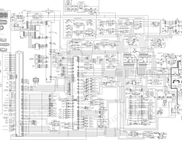
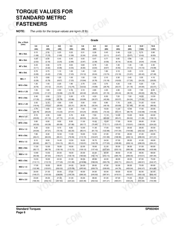
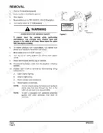
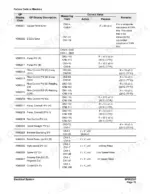
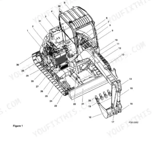
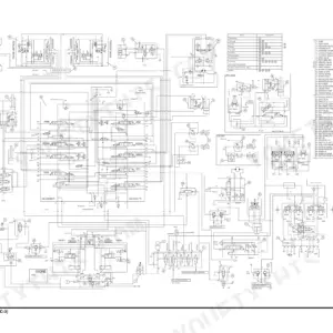
Looking for the Doosan DX160LC-3 shop manual PDF? All 891 pages of this factory shop manual (OEM #950106-01172E) cover your DX160LC-3 excavator from the swing bearing down to the track assembly. Inside: a complete hydraulic schematic with troubleshooting, testing, and adjustment procedures, full electrical schematics for the starting, charging, preheating, and monitoring circuits, and page after page of standard torque tables. You also get step-by-step teardown and reassembly for the main pump, swing motor, travel device, cylinders, and main control valve. Torque the main pump drive coupling bolts to 21-23 kg•m, and the travel motor frame and sprocket mounts to 25.7 ±4.0 kg•m. No more chasing pilot-pressure problems with borrowed numbers. Bookmarked with a full text layer; jump straight to any section or search any spec by keyword, right beside the machine.
What's Inside This Doosan DX160LC-3 Manual
| System | Pages | Key Topics |
|---|---|---|
| Safety | 5-72 | Track Excavator Maintenance Safety |
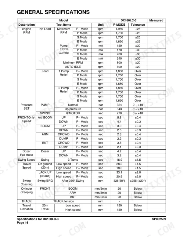
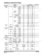
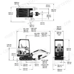
| Specifications | 73-102 | Specifications for DX160LC-3, General Dimensions, Working Range, General Specifications, Engine Performance Curves, Performance Tests |
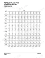
| General Maintenance | 103-140 | General Maintenance Instructions, Standard Torques |
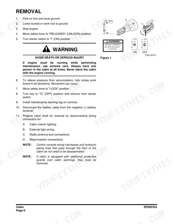
| Upper Structure | 141-242 | Cabin, Counterweight, Fuel Tank, Fuel Transfer Pump, Swing Bearing, Swing Reduction Gear |
| Lower Structure and Chassis | 243-276 | Track Assembly |
| Engine and Drivetrain | 277-306 | Engine Coolant Heater, Drive Coupling (Main Pump) |
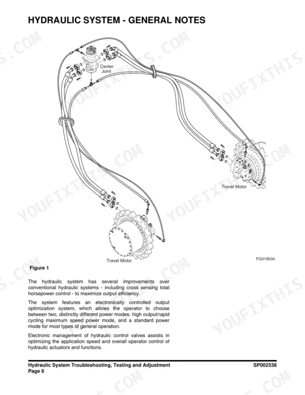
| Hydraulic System Troubleshooting, Testing and Adjustment | 307-342 | Operation of Working Components, Pilot Pressure, Power Mode Valve, Pressure Up Valve, Pump Input Power Control, Swing System Troubleshooting |
| Accumulator | 343-350 | Accumulator General Description, Precharge Pressure, Specifications |
| Center Joint (Swivel) | 351-364 | Center Joint Inspection, Testing, Disassembly, Reassembly |
| Cylinders | 365-404 | Cylinder Theory of Operation, Disassembly, Reassembly, Special Tools, Maintenance Standards |
| Swing Motor | 405-440 | Swing Motor Specifications, Construction, Principles of Working, Troubleshooting, Disassembly, Reassembly |
| Travel Device | 441-500 | Travel Device Basic Structure, Operation Principle, Disassembly, Reassembly, Performance Test |
| Main Pump | 501-538 | Main Pump General Description, Pump Regulator Operation, Disassembly, Reassembly, Performance Characteristics |
| Gear Pump | 539-550 | Single Gear Pump Disassembly, Driveshaft and Seal Handling, Reassembly |
| Main Control Valve | 551-602 | Theory of Operation, Composite Operation, Antidrift Valve, Main Relief Valve, Overload Relief Valve, Negacon Relief Valve, Adjusting Relief Valve |
| Remote Control Valve (Work Lever / Joystick) | 603-624 | Theory of Operation, Parts List, Specifications and Torques, Disassembly, Reassembly, Start-Up Procedures |
| Travel Control Valve (with Damper) | 625-652 | Pressure Reducing Valve, Damper Mechanism Theory, Causes of Faults and Measures, Wear Limits and Tolerances, Removal and Installation |
| Solenoid Valve Assembly | 653-664 | 5-Solenoid Valve Parts List, Functions of the Assembly, Solenoid Valve Diagram, Check Points and Solutions for Problems |
| Breaker EPPR Valve (Option) | 665-676 | Structure and Parts List, Functions and Operation, Maintenance, Disassembly, Assembly |
| Dozer Valve | 677-690 | Structure Diagram, Performance Specification, Hydraulic Pressure Circuit Diagram, Parts List, Disassembly and Assembly |
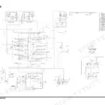
| Hydraulic Schematic (DX160LC-3) | 691-699 | Main Pump and Pilot Filter, Solenoid and Accumulator Circuits, Joystick and Pedal Valves, Main Control Valve, Boom Arm and Bucket Cylinders, Swing and Travel Devices, Center Joint, Oil Cooler and Full Flow Filter, Dozer and Smart Boom Circuits |
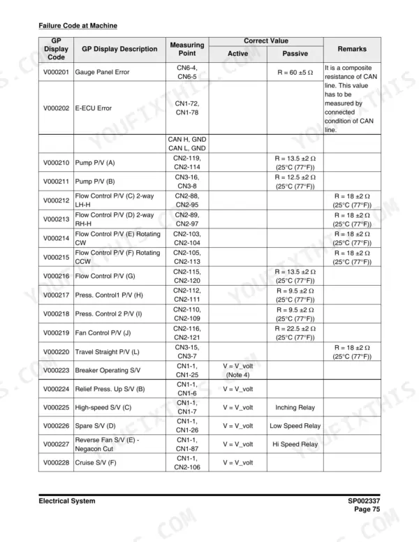
| Electrical System | 700-857 | Electrical Supply System, Engine Starting Circuit, Engine Preheating System, Charging System, Monitoring System, EPOS Electronic Hydraulic Control, Engine Control System, Engine Overheat Protection, Fault Code Tables |
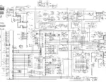
| Electrical Schematic | 858-865 | Battery and Charging Circuits, Starting and Auto Shutoff Unit, Engine Control and Air Flow Meter, EPOS and Auxiliary Mode Wiring, A/C and Blower Circuits, Lighting and Beacon, Alarm Buzzer and Relays, AMP and Bosch Connector Pinouts |
| Attachments | 866-891 | Boom and Arm, Bucket |
Quick Reference Specifications
| Specification | Value | Page |
|---|---|---|
| Fuel pump thermal limiter open temperature | 150 ±5°C (302 ±41°F) | p. 190 |
| Fuel pump thermal limiter reactivation temperature | 143°C (289°F) | p. 190 |
| Drive coupling (main pump) bolt torque, Ta | 21 - 23 kg•m | p. 305 |
| Drive coupling (main pump) bolt torque, Tb | 10 - 12 kg•m | p. 305 |
| Travel device frame and sprocket mount bolt torque, M16 | 25.7 ±4.0 kg•m | p. 459 |
| Pilot pressure at pump | 40 ±5 kg/cm2 (569 ±71 psi) | p. 324 |
| Pilot pressure at joystick | 23.5 ±1.5 kg/cm2 (334 ±21 psi) | p. 324 |
| Air cleaner replacement period (monitor default) | 2,000 hr | p. 736 |
| Return filter replacement period (monitor default) | 1,000 hr | p. 736 |
| Pilot filter replacement period (monitor default) | 1,000 hr | p. 736 |
| Engine oil filter replacement period (monitor default) | 500 hr | p. 736 |
| Oil Pressure Sensor (150 kPa) | 0.921 ±0.07 V | p. 779 |
| Oil Pressure Sensor (500 kPa) | 2.395 ±0.06 V | p. 779 |
| Crankshaft Sensor Resistance | 860 Ω ±10% (at 20°C) | p. 781 |
| Cab air filter cleaning interval | 500 hours | p. 819 |
Doosan DX160LC-3 Common Problems This Manual Covers
Doosan DX160LC-3 digs slow, boom and arm feel weak, pump whines under load
Check pilot pressure at the pump first: it should read 40 ±5 kg/cm2 per the test data on page 324. Then verify main relief pressure at 330 kg/cm2 for working and travel, 350 kg/cm2 with pressure up engaged. If both check out, replace the hydraulic return filter; the monitor carries a 1,000 hour default replacement period for it anyway.
Manual Section: Hydraulic System Troubleshooting, Testing and Adjustment p. 336Engine cranks but will not start, and the monitor logs engine fault code E520199
Test the crankshaft position sensor before throwing parts at it. Measure resistance across the sensor pins: spec is 860 Ω ±10% at 20°C, listed on page 781. The same table notes that with this fault the engine keeps running on the camshaft sensor signal but cannot be restarted once it has been shut down, which is exactly the no-start symptom. Out of range, replace the sensor. In range, inspect the harness and connector for chafing, then check battery ground straps for corrosion and tight contact.
Manual Section: Electrical System p. 781Low oil pressure warning at idle with engine fault code E000100, but the engine sounds normal
Verify actual pressure with a mechanical gauge before condemning the engine. If real pressure is good, test sensor output voltage: 0.921 ±0.07 V at 150 kPa and 2.395 ±0.06 V at 500 kPa, per page 779. Replace the sensor if readings drift outside spec. Keep the engine oil filter on its 500 hour interval.
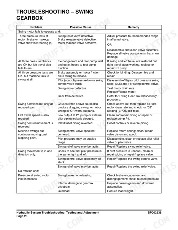
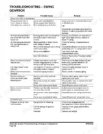
Manual Section: Electrical System p. 779Swing is jerky with grinding noise from the reduction gear during rotation
Drain the swing reduction gearbox and inspect the old oil for metal flakes. Refill through the oil nipple with 2.4 liters of EP80W/90 gear oil, as shown on page 240. If grinding continues, pull the reduction unit and inspect bearings and gear teeth; swing reduction bearings are a known wear item on these machines.
Manual Section: Upper Structure p. 240Engine overheats and loses power during heavy digging work in warm weather
Read what the machine is doing first. Page 808 states that above 107°C (225°F) coolant temperature the engine controller signals the EPOS controller, which lights the warning lamp and buzzer and drops the machine to standard power mode at low engine speed, so the power loss is the protection system working. Normal operation resumes below 95°C (203°F). Clean the cooling package and check fan belt tension before anything else, blow the radiator and oil cooler out from the fan side, and inspect the intake tract for collapsed or split hoses. Check the air cleaner counter too; the monitor carries a 2,000 hour default replacement period for it on page 736.
Manual Section: Electrical System p. 808Frequently Asked Questions
How do I reset the operation hour for a filter or oil change on the Doosan DX160LC-3?
To reset the operation hour, turn the jog switch to locate the cursor on the desired item. Click the jog switch once to display the selection screen at the bottom right. Click the jog switch again to display the screen to select the operation hour reset, then turn the jog switch to 'YES' and click to confirm. p. 735
What is the fuel tank capacity for the DX160LC-3?
The fuel tank capacity for the DX160LC-3 is 267 liters (70.5 U.S. gal). p. 173
What is the tightening torque for the main pump regulator mounting bolts?
The regulator mounting bolts (412, 413) are uneven in length and must be replaced to their proper location. The manual does not provide a specific torque value for these bolts, but emphasizes they must be replaced to their original positions. p. 536
What is the correct torque for the travel motor mounting bolts?
The tightening torque for the M16 (P2.0) bolts used for both the frame mount and sprocket mount is 25.7 ±4.0 kg•m. p. 459
What is the procedure for priming the fuel system if the engine does not start?
To prime the fuel system, loosen the plug (1, Figure 23) on top of the fuel filter head. Pump the hand-operated primer pump (2, Figure 23) until fuel is present at the plug hole, then tighten the plug. Continue pumping until strong resistance is felt. p. 181
Is this Doosan DX160LC-3 manual a PDF I download?
Instant PDF download. You get the full 891-page searchable Shop Manual immediately after payment. Open it on your laptop, tablet, or phone right in the shop.
Is printing allowed for this Doosan DX160LC-3 Shop Manual?
Yes. Print a chapter or just the pages for the job at hand, for use in your own shop. Any home or office printer works.







Reviews
There are no reviews yet.