
Part of the Doosan Repair Manuals.
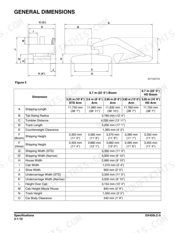
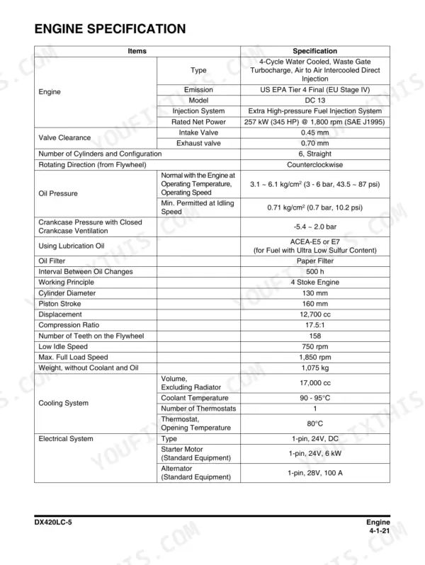
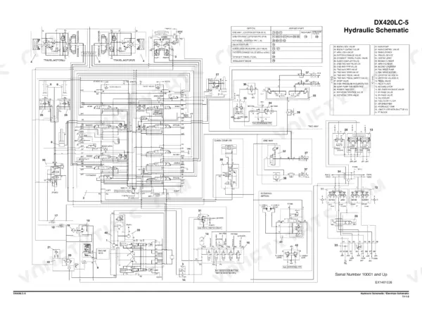
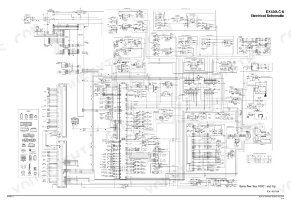
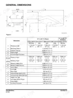
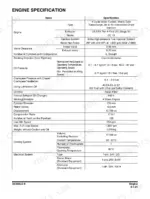
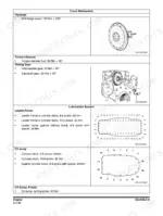
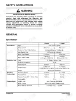
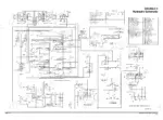
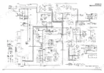
This is the factory shop manual for the Doosan DX420LC-5 crawler excavator, publication 950106-01020E, 1st Edition April 2014. It covers the whole machine: the Scania-built Doosan DC 13 engine rated 257 kW (345 HP) at 1,800 rpm with its Tier 4 Final aftertreatment, the main pump, main control valve, swing device and travel motors with disassembly, parts lists and section views, plus cabin, ROPS, swing bearing, boom and arm removal, and full electrical coverage. Machine specs like the 3,760 mm (12' 4") tail swing radius and 5,200 mm (17' 1") track length are on page 86. The final chapter carries the oversize hydraulic and electrical schematic foldouts, pages 1573 and 1574.
What's Inside This Doosan DX420LC-5 Manual
| System | Pages | Key Topics |
|---|---|---|
| Safety | 7-74 | Track Excavator Maintenance Safety, Safety Messages, Safe Operation Is Operator's Responsibility, Know Your Machine, Proper Work Tools and Attachments, Pressurized Fluids |
| Specifications and General Maintenance | 75-144 | Specifications, General Description, Component Locations, General Dimensions, Working Range, General Specifications |
| Engine - Inspection to Tightening Torques | 145-200 | Engine, Overview, Inspection, Cleaning the Engine, Special Tools, Mounting the Engine in a Universal Stand |
| Engine - Cylinder | 201-255 | Cylinder, Cylinder Head, Valve Mechanism, Cylinder Block, Cylinder Liner, Flywheel Housing |
| Engine - Actuating System and Lubrication System | 256-325 | Actuating System, Camshaft, Connecting Rod, Crankshaft, Flywheel, Piston |
| Engine - Exhaust System | 326-414 | Exhaust System, General Information, T113, Exhaust Temperature Sensor Before Catalytic Converter, T115, NOx Sensor, T131 NOx Sensor, T116, Reductant Pick-Up Unit |
| Engine - Cooling System and Fuel System | 415-479 | Cooling System, Internal Cleaning of Cooling System, Charge Air Cooler, Charge Air Temperature Sensor, Charge Air Pressure Sensor, Coupling Coil for AC Compressor |
| Engine - Electrical System to Engine Coolant Heater (Option) | 480-564 | Electrical System, E44, Control Unit EMS, Control Unit EEC, Engine Speed Sensor, T110 Oil Level Sensor, T111, Fuel Pressure Sensor |
| Upper Structure - Cabin to Fuel Tank | 565-632 | Cabin, Cabin Identification, Roll-Over Protective Structure (ROPS), Removal, Installation, Dimensions of Cabin Glass |
| Upper Structure - Main Pump | 633-718 | Main Pump, Specifications, Overview, Hydraulic Circuit, Parts List, Theory of Operation |
| Upper Structure - Drive Coupling (Main Pump) | 719-730 | Drive Coupling (Main Pump), Specification, Parts List, Section View, Tools, Disassembly |
| Upper Structure - Main Control Valve | 731-818 | Main Control Valve, Specification, Overview, Hydraulic Circuit, Parts List, Theory of Operation |
| Upper Structure - Swing Device | 819-876 | Swing Device, Specification, Overview, Hydraulics Circuit, Parts List, Theory of Operation |
| Upper Structure - Fan Pump for Oil Cooler | 877-914 | Fan Pump for Oil Cooler, Specification, Overview, Parts List, Theory of Operation, Maintenance Guidelines |
| Upper Structure - Fan Motor for Oil Cooler to Joystick Valve (Work Lever) | 915-972 | Fan Motor for Oil Cooler, Specification, Overview, Parts List and Section View, Precaution, Tools |
| Upper Structure - Travel Control Valve (with Damper) to Accumulator | 973-1028 | Travel Control Valve (with Damper), Specification, Overview, Parts List, Theory of Operation, Tools and Torques |
| Lower Structure and Chassis | 1029-1162 | Swing Bearing, General Description, Parts List, Maintenance Guidelines, Disassembly, Reassembly |
| Front | 1163-1222 | Boom and Arm, Specifications, Removal, Arm Removal, Boom Removal, Installation |
| Hydraulic System | 1223-1312 | General Description, Hydraulic Schematic, Hydraulic Component and Oil Flow, Hydraulic Component, Main Oil Line |
| Electrical System | 1313-1484 | Electrical Supply System, Engine Starting Circuit, Start Operation, After Start, Engine Stop |
| Options | 1485-1568 | One Way, General Description, Theory of Operation, Hydraulic Circuit, Caution for Installation, Installation Procedure |
| Schematic | 1569-1574 | Hydraulic Schematic / Electrical Schematic |
Quick Reference Specifications
| Specification | Value | Page |
|---|---|---|
| Engine model | Doosan DC 13 (built by Scania), US EPA Tier 4 Final (EU Stage IV) | p. 167 |
| Rated net power | 257 kW (345 HP) @ 1,800 rpm (SAE J1995) | p. 167 |
| Tail swing radius | 3,760 mm (12' 4") | p. 86 |
| Counterweight clearance | 1,265 mm (4' 2") | p. 86 |
| Track length | 5,200 mm (17' 1") | p. 86 |
| Undercarriage width, standard | 3,350 mm (11' 0") | p. 86 |
| Undercarriage width, narrow | 3,000 mm (9' 10") | p. 86 |
| Shoe width | 600 mm (2' 0") | p. 86 |
| Height over cab | 3,154 mm (10' 4") | p. 86 |
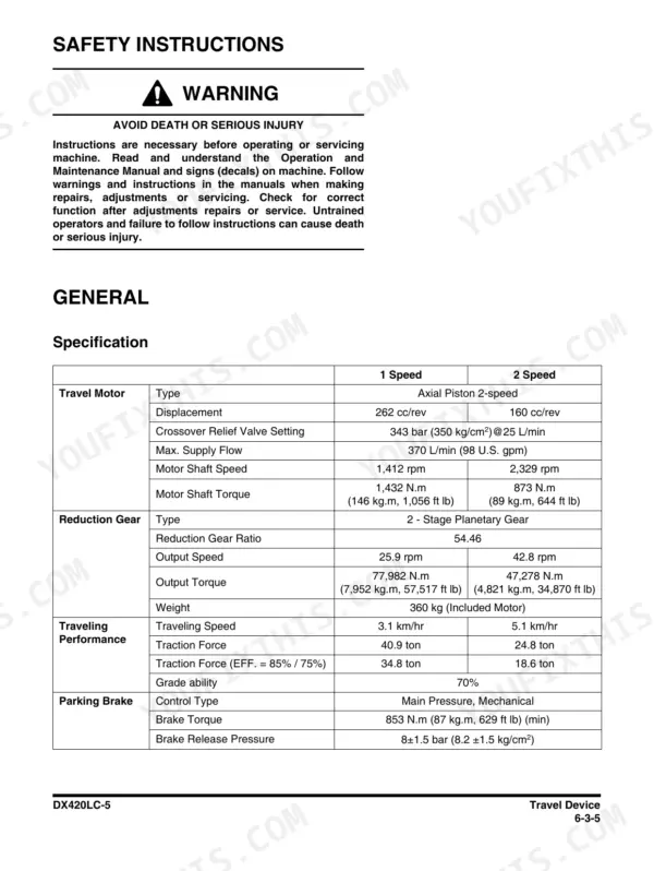
| Travel motor displacement and relief | 160 cc/rev, 343 bar (350 kg/cm²) at 25 L/min | p. 1065 |
| Swing motor test pressure | 196 bar (200 kg/cm²) at 8 rpm for the volumetric efficiency check | p. 1126 |
Doosan DX420LC-5 Common Problems This Manual Covers
Hydraulic functions turn slow, weak or noisy, with cavitation or overheating under load
Start with oil level, contamination and the return and air filters, then work the Main Pump section in Upper Structure: it carries the hydraulic circuit, parts list and theory of operation so you can judge internal leakage and wear before pulling the pump.
Manual Section: Upper Structure - Main Pump p. 1223Machine will not crank, cranks weak, or starting is intermittent
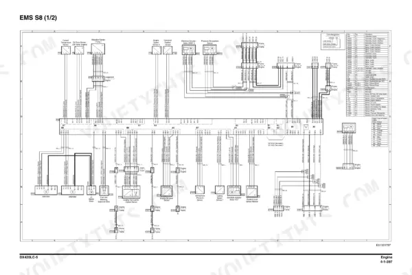
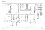
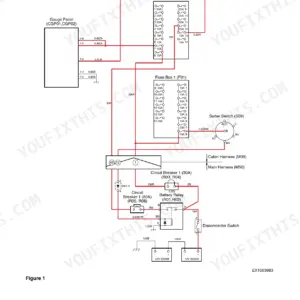
The Electrical System chapter walks the whole starting sequence: electrical supply system, engine starting circuit, start operation, after start and engine stop. Trace battery, grounds and starter feed against the electrical schematic on page 1574 and the A3 engine sheets at pages 543 to 548.
Manual Section: Electrical System p. 1029Track drive loss, jerky travel, or grinding from the final drives
Check travel relief first: the travel motor is 160 cc/rev with relief set at 343 bar (350 kg/cm2) at 25 L/min, page 1065. Then use the Travel Control Valve section, with its damper, parts list and theory of operation, to separate a valve fault from motor or gear wear.
Manual Section: Upper Structure - Travel Control Valve (with Damper) to Accumulator p. 1313Swing is rough, drifts, or the bearing growls under rotation
The Swing Device section gives the hydraulic circuit, parts list and theory of operation, and the volumetric efficiency check at 196 bar (200 kg/cm2) at 8 rpm on page 1126 tells you if the motor is worn. Bearing noise itself goes to the swing bearing coverage in Lower Structure and Chassis.
Manual Section: Upper Structure - Swing Device p. 1163Frequently Asked Questions
What is the hydraulic pressure setting for a Doosan DX420LC-5?
The manual prints relief and test pressures per component, in bar and kg/cm2 together as Doosan wrote them. Example: the travel motor is 160 cc/rev with relief at 343 bar (350 kg/cm2) at 25 L/min, on page 1065. The swing motor volumetric efficiency check runs at 196 bar (200 kg/cm2) at 8 rpm, page 1126. Each Upper Structure section (Main Pump, Main Control Valve, Swing Device) opens with its own specification table. p. 167
How do I clear fault codes or reset the service indicator on a DX420LC-5?
The Electrical System chapter is where the diagnostics live: supply system, starting circuit, and the monitor side of the machine. This is a Tier 4 Final machine with EMS and EEC control units, so faults are read and handled through that chapter, not by guesswork. I will not quote code numbers here because no code table is grounded in this listing - work from the electrical chapter and the schematic on page 1574. p. 86
Are the torque specs in this manual, like for track roller bolts?
Yes. The engine section runs from inspection through tightening torques, and the component sections (drive coupling, swing device, travel control valve) each carry their own tools and torques pages. Undercarriage hardware is handled in the Lower Structure and Chassis chapter with the swing bearing disassembly and reassembly. I will not quote a bolt torque from memory - pull it from the section for the exact joint you are on. p. 1573
Does it include the full hydraulic and electrical schematics?
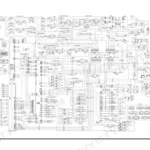
It does, as oversize foldouts in the final Schematic chapter: the hydraulic schematic is page 1573 and the electrical schematic page 1574. On top of that, there are six A3 electrical sheets at pages 543 to 548 inside the engine section covering the Scania-side engine wiring. Between those and the Hydraulic System chapter's oil flow descriptions, you can trace any circuit on the machine. p. 543
Does this manual cover the Tier 4 aftertreatment on the DC 13 engine?
Yes. The engine is the Doosan DC 13 built by Scania, US EPA Tier 4 Final (EU Stage IV), and the exhaust system section uses Scania component designations: T113 exhaust temperature sensor before the catalytic converter, the T115 and T131 NOx sensors, and the T116 reductant pick-up unit. Those are component numbers, not trouble codes. The electrical section covers the EMS and EEC control units and their sensors. p. 180






Reviews
There are no reviews yet.