

Part of the Doosan Repair Manuals.
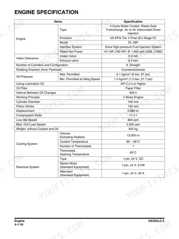
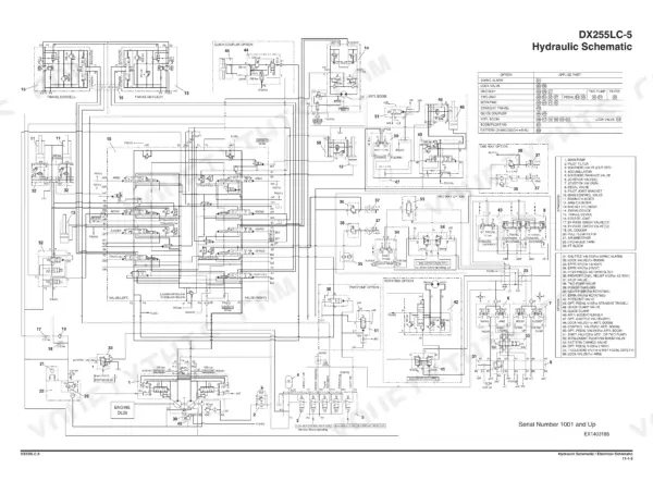
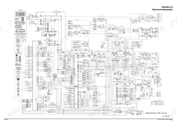
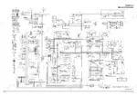
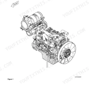
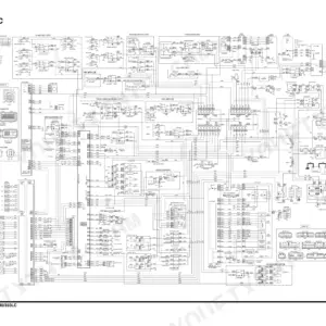
Factory shop manual for the Doosan DX255LC-5 crawler excavator, publication 950106-01505E, 1st Edition August 2014. This is the Tier 4 Final machine with the DL 06P engine, rated 141 kW (190 HP) @ 1,900 rpm (SAE J1995), and this book is written for the wrench, not the operator. You get full teardown coverage of the main pump and its drive coupling, main control valve, swing device, joystick and travel pilot valves, solenoid and EPPR valves, swing bearing, cabin/ROPS, and both the one-piece and two-piece boom. Specification tables, parts lists, section views, and theory of operation run through every chapter, and the back of the book carries oversize foldouts: the hydraulic schematic on page 1315 and the electrical schematic on page 1316.
What's Inside This Doosan DX255LC-5 Manual
| System | Pages | Key Topics |
|---|---|---|
| Safety | 7-74 | Track Excavator Maintenance Safety, Safety Messages, Safe Operation Is Operator's Responsibility, Know Your Machine, Proper Work Tools and Attachments, Pressurized Fluids |
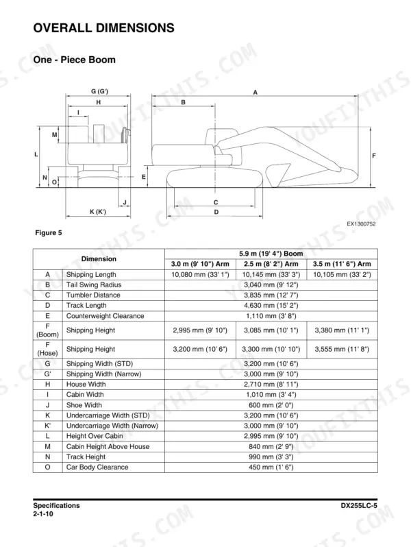
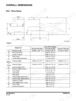
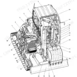
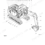
| Specifications | 75-108 | General Description, Component Locations, Overall Dimensions, One - Piece Boom, Two - Piece Boom |
| General Maintenance | 109-146 | General Maintenance Instructions, Welding Precautions and Instructions, Hydraulic System - General Precautions, Maintenance Service and Repair Procedure, General Precautions, Hydraulic System Cleanliness and Oil Leaks |
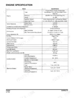
| Engine | 147-344 | Overview, General Information, General Description, Engine Maintenance, Inspection and Repair of the Engine |
| Upper Structure - Cabin | 345-372 | Cabin, Cabin Identification, Roll-Over Protective Structure (ROPS), Removal, Installation, Dimensions of Cabin Glass |
| Upper Structure - Counterweight and Hydraulic Oil Tank | 373-400 | Counterweight, Warning for Counterweight and Front Attachment Removal, Removal, Installation, Hydraulic Oil Tank, Specification |
| Upper Structure - Fuel Tank | 401-416 | Fuel Tank, Specification, Parts List, Removal, Installation, Completing Work |
| Upper Structure - Main Pump | 417-480 | Main Pump, Axial Piston Pump, Specifications, Overview, Hydraulic Circuit, Parts List |
| Upper Structure - Drive Coupling (Main Pump) | 481-492 | Drive Coupling (Main Pump), Specification, Parts List, Section View, Tools, Disassembly |
| Upper Structure - Main Control Valve | 493-586 | Main Control Valve, Specification, Overview, Parts List, Theory of Operation, Cautions for Operation |
| Upper Structure - Swing Device | 587-648 | Swing Device, Specification, Overview, Parts List, Theory of Operation, Cautions for Operation |
| Upper Structure - Gear Pump (Rotation) | 649-662 | Gear Pump (Rotation), Specification, Overview, Location, Parts List, Single Gear Pump |
| Upper Structure - Joystick Valve (Work Lever) | 663-692 | Joystick Valve (Work Lever), Specifications, Overview, Parts List, Theory of Operation, Tools and Torques |
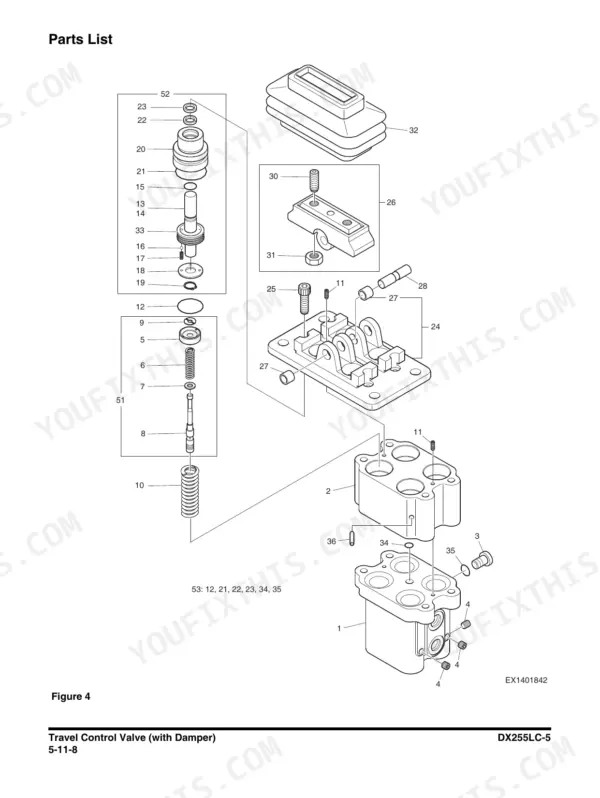
| Upper Structure - Travel Control Valve (with Damper) | 693-720 | Travel Control Valve (with Damper), Specification, Overview, Parts List, Theory of Operation, Tools and Torques |
| Upper Structure - Solenoid Valve | 721-732 | Solenoid Valve, Specification, Overview, Parts List, Theory of Operation, Disassembly and Reassembly |
| Upper Structure - EPPR Valve and Accumulator | 733-748 | EPPR Valve, Specification, Overview, Hydraulic Circuit, Troubleshooting, Accumulator |
| Lower Structure and Chassis | 749-884 | Swing Bearing, General Description, Parts List, Maintenance Guidelines, Disassembly, Reassembly |
| Front | 885-946 | Boom and Arm, Specifications, One - Piece Boom, Two - Piece Boom, Removal, Arm Removal |
| Hydraulic System | 947-1028 | General Description, Hydraulic Schematic, Hydraulic Component and Oil Flow, Hydraulic Components, Main Oil Circuit |
| Electrical System | 1029-1218 | Electrical Supply System, Engine Starting Circuit, Start Operation, After Start, Engine Preheating System |
| Options | 1219-1310 | One Way, General Description, Theory of Operation, Hydraulic Circuit, Caution for Installation, Installation Procedure |
| Schematic | 1311-1316 | Hydraulic Schematic / Electrical Schematic, Hydraulic Schematic, Electrical Schematic |
Quick Reference Specifications
| Specification | Value | Page |
|---|---|---|
| Engine model | Doosan DL 06P, US EPA Tier 4 Final (EU Stage IV) | p. 166 |
| Rated net power | 141 kW (190 HP) @ 1,900 rpm (SAE J1995) | p. 166 |
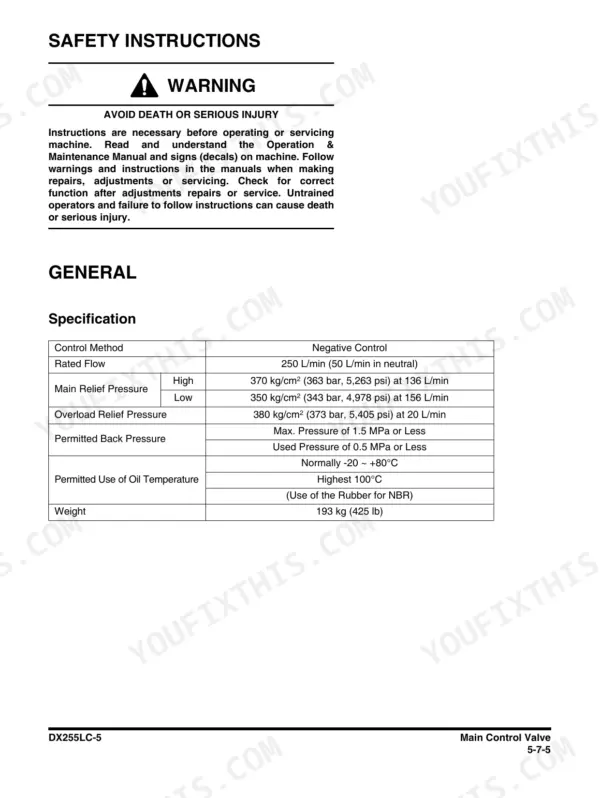
| Main relief pressure | high 370 kg/cm² (363 bar, 5,263 psi) at 136 L/min; low 350 kg/cm² | p. 497 |
| Main pump rated flow | 250 L/min (50 L/min in neutral) | p. 497 |
| Tail swing radius | 3,040 mm (9' 12") | p. 86 |
| Counterweight clearance | 1,110 mm (3' 8") | p. 86 |
| Track length | 4,630 mm (15' 2") | p. 86 |
| Undercarriage width, standard | 3,200 mm (10' 6") | p. 86 |
| Undercarriage width, narrow | 3,000 mm (9' 10") | p. 86 |
| Shoe width | 600 mm (2' 0") | p. 86 |
| Shipping length | 10,080 mm (33' 1") | p. 86 |
| Height over cabin | 2,995 mm (9' 10") | p. 86 |
Doosan DX255LC-5 Common Problems This Manual Covers
Engine cranks but will not start, or only fires after long cranking, usually after a filter change or running the tank low.
Suspect air in the fuel system or a saturated fuel filter/water separator before anything else. The Engine chapter's maintenance and inspection sections cover DL 06P fuel system service, and the Fuel Tank section gives removal, installation, and completing work steps so you can bleed the system and verify the fix.
Manual Section: Engine / Upper Structure - Fuel Tank p. 497Hydraulic functions slow, weak, or noisy, or the monitor flags a clogged return filter.
Start with oil level and filter condition before condemning the pump. The Hydraulic System chapter maps component and oil flow through the main oil circuit, while General Maintenance's Hydraulic System Cleanliness and Oil Leaks section explains the contamination discipline that keeps a 250 L/min axial piston pump alive.
Manual Section: Hydraulic System / General Maintenance p. 1231Vibration, rattle, or wobble from the engine-to-pump area, often mistaken for engine trouble.
That is usually the flex coupling between the DL 06P and the main pump wearing out or its bolts backing off. The Drive Coupling (Main Pump) section gives the specification, parts list, section view, required tools, and disassembly procedure so you can inspect the element and re-torque correctly instead of guessing.
Manual Section: Upper Structure - Drive Coupling (Main Pump) p. 1035Oil leaks at the swing motor, main pump drain lines, or hose fittings, sometimes with metal in the oil.
External leaks are seal and fitting work, but metal contamination points to internal wear. The Swing Device section covers specification, parts list, theory of operation, and cautions for operation, and the Hydraulic Oil Tank section under Upper Structure covers the tank and its specification so you can drain, inspect, and refill clean.
Manual Section: Upper Structure - Swing Device / Counterweight and Hydraulic Oil Tank p. 219Frequently Asked Questions
My DX255LC-5 cranks but will not start. Does this manual cover priming the fuel system?
Yes. On this machine a no-start after a filter change or a run-dry is almost always air in the fuel system, and the Engine chapter covers maintenance, inspection, and repair of the DL 06P including fuel filter and water separator service. The Fuel Tank section under Upper Structure gives the parts list, removal, and installation steps so you can chase the air leak back to its source instead of cranking the batteries flat. p. 166
Does it show the hydraulic pressure specs so I can check and reset the main relief?
The specification pages print the numbers you need: main relief is 370 kg/cm² (363 bar, 5,263 psi) high stage at 136 L/min and 350 kg/cm² low stage, with the main pump rated at 250 L/min and 50 L/min in neutral (page 497). The Main Control Valve and Main Pump sections give the theory of operation behind those settings, so you know what you are adjusting and why before you touch a relief cartridge. p. 497
Can I use this book to work through electrical faults and monitor warnings?
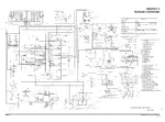
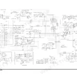
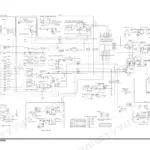
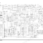
The Electrical System chapter is where the diagnostic material sits: electrical supply system, engine starting circuit, start operation, after start, and the engine preheating system. Pair that with the full electrical schematic foldout on page 1316 and you can trace any circuit on the machine wire by wire. That is how you actually find a fault - at the connector with a meter, not by guessing. p. 1316
My machine has the two-piece boom. Is that version covered or just the standard boom?
Both. The Specifications chapter lists dimensions for the one-piece and two-piece boom, and the Front chapter carries removal and installation procedures for each, plus arm removal. Overall dimensions like the 3,040 mm tail swing radius and 10,080 mm shipping length are in the dimension tables on page 86, which matters when you are planning transport or working tight quarters. p. 86
Are the full schematics included, or do I need a separate print set?
They are in the book. The final Schematic chapter carries both as oversize foldouts: the complete hydraulic schematic on page 1315 and the complete electrical schematic on page 1316. Between those two pages and the per-component hydraulic circuits printed in the pump, control valve, swing device, and EPPR sections, you can follow oil or current anywhere on the machine. p. 1315





Reviews
There are no reviews yet.