
Part of the Doosan Repair Manuals.
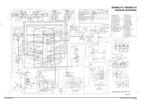
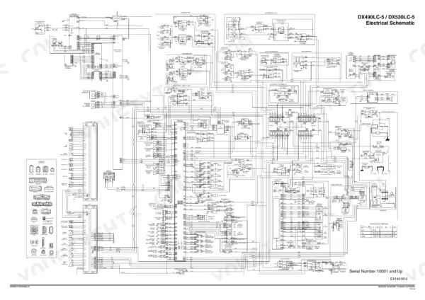
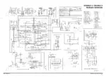
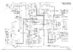
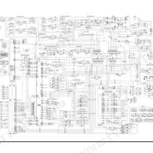
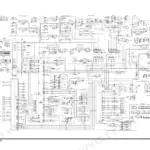
This is the factory shop manual Doosan printed in May 2014 (publication 950106-01005E) for the DX490LC-5 and DX530LC-5 crawler excavators, the Tier 4 Final machines running the Scania-built Doosan DC 13 rated 283 kW (380 HP) at 1,800 rpm. It covers the engine down to crankshaft, liners and the SCR/reductant plumbing, then the whole hydraulic side: main pump, main control valve, swing device, fan pump, joysticks and EPPR valves, with theory of operation and parts lists for each. Undercarriage, swing bearing, track assembly, boom/arm/bucket removal, electrical troubleshooting with the E-code table, and full foldout hydraulic (page 1579) and electrical (page 1580) schematics round it out. 1,580 pages of what the dealer techs actually use.
What's Inside This Doosan DX490LC-5, DX530LC-5 Manual
| System | Pages | Key Topics |
|---|---|---|
| Safety | 7-74 | Track Excavator Maintenance Safety, Safety Messages, Safe Operation Is Operator's Responsibility, Know Your Machine, Proper Work Tools and Attachments, Pressurized Fluids |
| Specifications | 75-112 | General Description, Component Locations, General Dimensions, Variable Track |
| General Maintenance and Standard Torques | 113-150 | General Maintenance Instructions, Welding Precautions and Instructions, Hydraulic System - General Precautions, Maintenance Service and Repair Procedure, General Precautions, Hydraulic System Cleanliness and Oil Leaks |
| Engine - Identification, Specifications and Tightening Torques | 151-206 | Engine, Overview, Inspection, Cleaning the Engine, Special Tools, Mounting the Engine in a Universal Stand |
| Engine - Cylinder Head and Block | 207-261 | Cylinder, Cylinder Head, Valve Mechanism, Cylinder Block, Cylinder Liner, Flywheel Housing |
| Engine - Actuating and Lubrication Systems | 262-331 | Actuating System, Camshaft, Connecting Rod, Crankshaft, Flywheel, Piston |
| Engine - Exhaust and Cooling Systems | 332-436 | Exhaust System, General Information, T113, Exhaust Temperature Sensor Before Catalytic Converter, T115, NOx Sensor, T131 NOx Sensor, T116, Reductant Pick-Up Unit |
| Engine - Fuel System | 437-485 | Fuel System, General Information, Accumulator, Fuel Manifold, Overflow Valve, Feed Pump |
| Engine - Electrical System | 486-554 | Electrical System, E44, Control Unit EMS, Control Unit EEC, Engine Speed Sensor, T110 Oil Level Sensor, T111, Fuel Pressure Sensor |
| Engine Coolant Heater | 555-570 | Engine Coolant Heater (Option), Disassembly and Assembly, Changing the Circulating Pump, Changing the Temperature Limiter, Changing the Temperature Sensor, Changing the Combustion Air Fan |
| Upper Structure - Cabin, Counterweight and Tanks | 571-638 | Cabin, Cabin Identification, Roll-Over Protective Structure (ROPS), Removal, Installation, Dimensions of Cabin Glass |
| Main Pump and Drive Coupling | 639-736 | Main Pump, Specifications, Overview, Hydraulic Circuit, Parts List, Theory of Operation |
| Main Control Valve | 737-824 | Specification, Overview, Hydraulic Circuit, Parts List, Theory of Operation |
| Swing Device | 825-882 | Specification, Overview, Hydraulics Circuit, Parts List, Theory of Operation |
| Fan Pump, Fan Motor and Gear Pump | 883-948 | Fan Pump for Oil Cooler, Specification, Overview, Parts List, Theory of Operation, Maintenance Guidelines |
| Joystick, Travel Control, Solenoid and EPPR Valves | 949-1026 | Joystick Valve (Work Lever), Specifications, Overview, Parts List, Theory of Operation, Tools and Torques |
| Accumulator | 1027-1034 | Specifications |
| Lower Structure - Swing Bearing, Center Joint, Travel Device | 1035-1136 | Swing Bearing, General Description, Parts List, Maintenance Guidelines, Disassembly, Reassembly |
| Track Assembly | 1137-1170 | Track Tension, Track Shoes and Links, Parts List, Track Removal, Track Installation |
| Front - Boom, Arm, Bucket and Cylinders | 1171-1228 | Boom and Arm, Specifications, Removal, Arm Removal, Boom Removal, Installation |
| Hydraulic System - Operation, Testing, Adjustment and Troubleshooting | 1229-1318 | Hydraulic System, General Description, Hydraulic Schematic, Hydraulic Component and Oil Flow, Hydraulic Component, Main Circuit |
| Electrical System and Troubleshooting | 1319-1490 | Electrical System, Electrical Supply System, Engine Starting Circuit, Start Operation, After Start, Engine Stop |
| Options - One Way, Two Way, Rotating and Quick Coupler | 1491-1574 | One Way, General Description, Theory of Operation, Hydraulic Circuit, Caution for Installation, Installation Procedure |
| Hydraulic and Electrical Schematics | 1575-1580 | Hydraulic Schematic / Electrical Schematic |
Quick Reference Specifications
| Specification | Value | Page |
|---|---|---|
| Engine model | Doosan DC 13 (Scania), 4-cycle water cooled, turbocharged | p. 173 |
| Emission level | US EPA Tier 4 Final (EU Stage IV) | p. 173 |
| Rated net power | 283 kW (380 HP) @ 1,800 rpm (SAE J1995) | p. 173 |
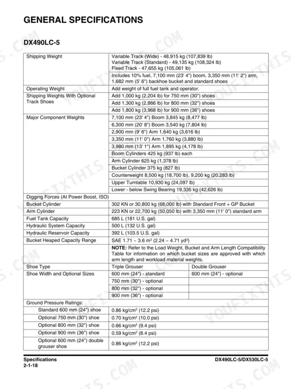
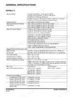
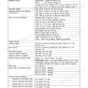
| Shipping weight, DX490LC-5 | 48,915 kg (107,839 lb) variable track wide; 47,655 kg (105,061 lb) fixed track | p. 94 |
| Shipping weight, DX530LC-5 | 51,484 kg (113,503 lb) variable track wide | p. 96 |
| Bucket digging force | 302 kN or 30,800 kg (68,000 lb), standard front with GP bucket | p. 94 |
| Arm digging force | 223 kN or 22,700 kg (50,050 lb) with 3,350 mm (11' 0") arm | p. 94 |
| Fuel tank capacity | 685 L (181 U.S. gal) | p. 94 |
| Hydraulic system capacity | 500 L (132 U.S. gal) | p. 94 |
| Hydraulic reservoir capacity | 392 L (103.5 U.S. gal) | p. 94 |
| Counterweight | 8,500 kg (18,700 lb) or 9,200 kg (20,283 lb) | p. 94 |
| Upper turntable weight | 10,930 kg (24,097 lb) | p. 94 |
| Lower structure weight, below swing bearing | 19,335 kg (42,626 lb) | p. 94 |
| Tail swing radius | 3,800 mm (12' 6") | p. 86 |
| Undercarriage width, variable track | 3,900 mm (12' 10") extended, 3,340 mm (10' 11") retracted | p. 86 |
| Bucket heaped capacity range | SAE 1.71 ~ 3.6 m³ (2.24 ~ 4.71 yd³) | p. 94 |
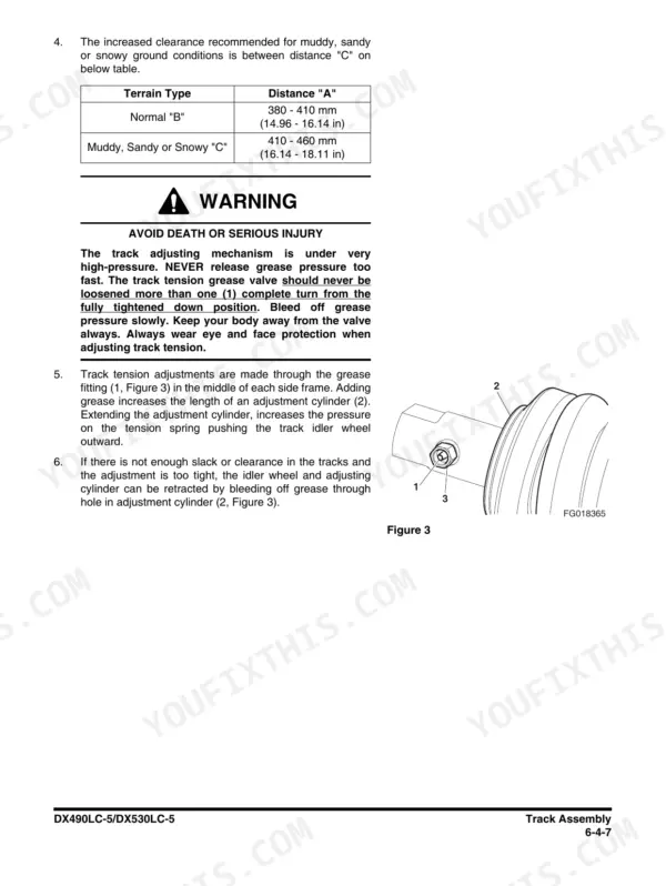
| Track tension, recommended distance "A" | 380 - 410 mm (14.96 - 16.14 in) normal; 410 - 460 mm (16.14 - 18.11 in) muddy, sandy or snowy | p. 1143 |
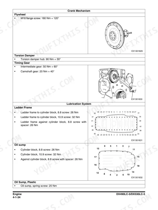
| Flywheel screw torque | M18 flange screw: 180 Nm + 120° | p. 186 |
| Cylinder head screw torque | Torx screw: 50 Nm + 90°, check torque 170 Nm (screws reusable 3 times) | p. 183 |
| Boom and arm weights | 7,100 mm boom 3,845 kg (8,477 lb); 3,350 mm arm 1,760 kg (3,880 lb) | p. 94 |
Doosan DX490LC-5, DX530LC-5 Common Problems This Manual Covers
Engine derates or throws repeated aftertreatment codes on the Tier 4 Final DC 13, usually pointing at the NOx sensors, exhaust temperature sensors or the reductant system.
Start with the Exhaust and Cooling Systems chapter, which covers the T113 exhaust temperature sensor before the catalytic converter, the T115 and T131 NOx sensors and the T116 reductant pick-up unit, then match the panel E-code against the SPN table on pages 1394 to 1398 before replacing anything.
Manual Section: Engine - Exhaust and Cooling Systems p. 333Hard starting or rough running after fuel filter or injector work, from air left in the high pressure system or a leaking fuel pipe.
The Fuel System chapter details the accumulator, fuel manifold, overflow valve and feed pump with the correct service sequence, so you depressurize, reseal and bleed the common rail side properly instead of cranking the batteries flat hoping it self-primes.
Manual Section: Engine - Fuel System p. 437Weak digging force or sluggish, inconsistent boom and travel response as the machine ages.
Work through the Hydraulic System operation and testing chapter, which explains the main circuit and oil flow component by component and gives the test and adjustment procedures, then use the main pump and main control valve chapters, each with theory of operation and parts lists, to pin down whether it is pump wear, pilot pressure or a valve fault.
Manual Section: Hydraulic System - Operation, Testing, Adjustment and Troubleshooting p. 1275Intermittent electrical gremlins: sensor faults, random shutdowns, or a machine that cranks but will not start.
The Electrical System and Troubleshooting chapter walks the supply system and the complete starting circuit through start, after start and stop, and the foldout machine electrical schematic on page 1580 plus the six A3 engine sheets let you trace harness damage and ECU connections wire by wire.
Manual Section: Electrical System and Troubleshooting p. 1319Frequently Asked Questions
What does an error code like E000107 mean on a DX490LC-5 or DX530LC-5, and how do I look it up?
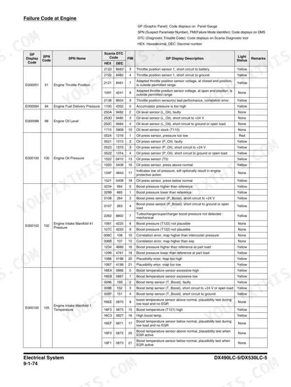
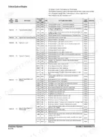
These machines show six-digit E-codes on the gauge panel, each paired with a J1939 SPN number and name, for example E000107 / SPN 107 / Engine Air Filter 1 Differential Pressure. The manual carries the full code table on pages 1394 to 1398 in the electrical troubleshooting chapter, and notes the same codes read out on the Scania Diagnostic tool. If someone quotes you a P-code for this machine, they are reading from the older Isuzu-engined DX490LC-3 book, which does not apply here. p. 1394
How do I clear a fault code after fixing the problem?
Most active codes go inactive on their own once the fault condition is gone and the key is cycled, but stored engine and aftertreatment faults on the DC 13 are read and cleared through the Scania Diagnostic tool, which the manual references alongside the E-code table. The real work is in the diagnosis: the electrical troubleshooting chapter walks each sensor circuit (engine speed sensor, T111 fuel pressure sensor, NOx sensors T115/T131 and the rest) so you fix the cause instead of chasing a code that keeps coming back. p. 1394
Are the engine torque specs in here, like cylinder head bolts?
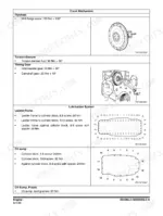
Yes, and pay attention to the format: Scania specs most of the big fasteners as a torque plus an angle, not a single number. The flywheel M18 flange screws, for example, are 180 Nm plus 120 degrees, and the torsion damper hub is 90 Nm plus 30 degrees (page 186). Cylinder head bolts follow the same torque-plus-angle staging, laid out step by step in the Cylinder Head and Block chapter. Do not let anyone hand you one collapsed number for these, you will either snap a bolt or leave the joint loose. p. 186
What is the correct track tension, and how do I adjust it?
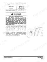
The Track Assembly chapter gives 380 to 410 mm (14.96 to 16.14 in) of measured clearance on normal ground, and a looser 410 to 460 mm (16.14 to 18.11 in) for muddy, sandy or snowy conditions so the track does not pack tight and eat the undercarriage. Adjustment is grease in or out of the track adjuster cylinder, and the same chapter covers shoes, links, and full track removal and installation if you are past adjusting and into replacing. p. 1143
Does this manual cover both the DX490LC-5 and DX530LC-5, and the variable track versions?
One book covers both machines. The specification chapter splits them where they differ: shipping weight is 48,915 kg for the DX490LC-5 variable track wide versus 51,484 kg for the DX530LC-5, counterweights run 8,500 or 9,200 kg, and there are two dedicated variable track sections with the full dimension tables, including undercarriage width of 3,900 mm wide retracting to 3,340 mm for transport. Shipping widths, boom and hose heights for every boom/arm combination are on page 86, which matters when you are permitting a lowboy load. p. 94







Reviews
There are no reviews yet.