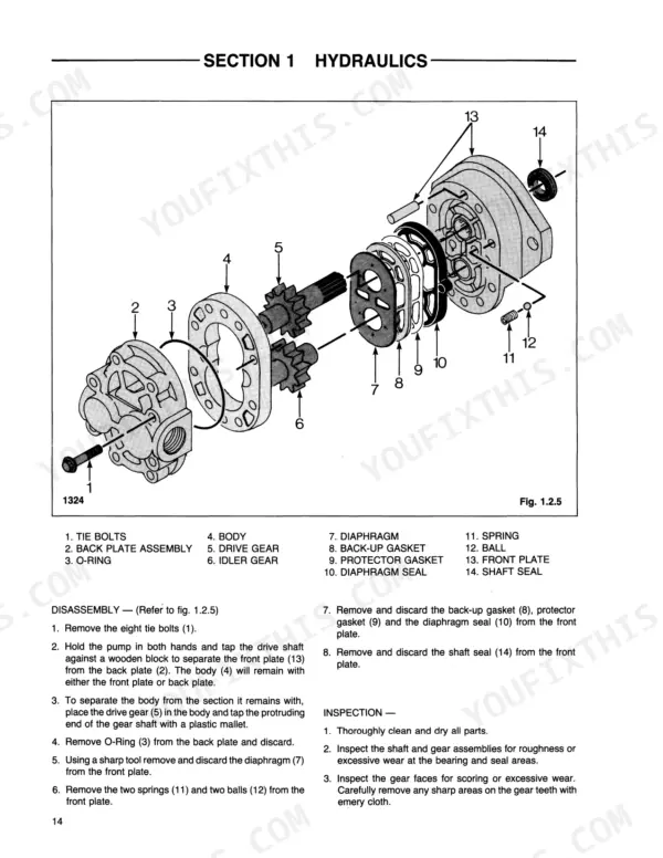
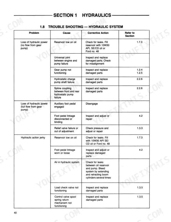
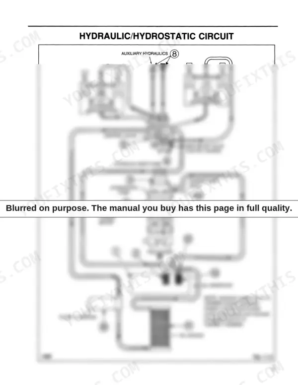
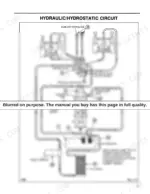
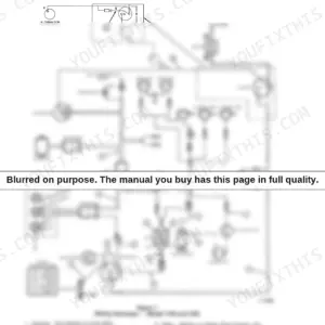
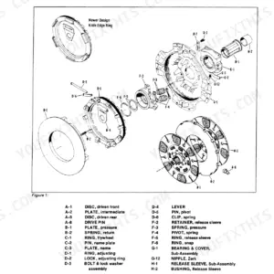
When your boom drifts under load or lift speed falls off, the fix starts with pressure numbers, and this Ford CL-35, CL-45 repair manual PDF has them: 306 pages of factory service data covering both compact loaders, OEM ID 40003510. Hydraulic schematics trace the circuit from gear pump through control valve to the boom and bucket cylinders, and wiring diagrams cover starting, charging and instrumentation when the electrical side acts up. Exploded views back up the teardown procedures across the Quick-Tach assembly, boom arms and engine overhaul, with troubleshooting charts and the preventative maintenance schedule rounding out the book. Set the relief valve against the rated 2150 PSI (148 bar), and torque the gear pump mounting bolts to 27-31 ft. lbs. (36.6-42 N.m.) going back together. Guessing costs you the wrong part and a second teardown. Bookmarked and text-searchable, this PDF puts the number in front of you and the loader back to lifting.
What's Inside This Repair Manual
| System | Pages | Key Topics |
|---|
| Hydraulic Circuit | 9-11 | Specifications, Control Functions, Maintenance Schedule |
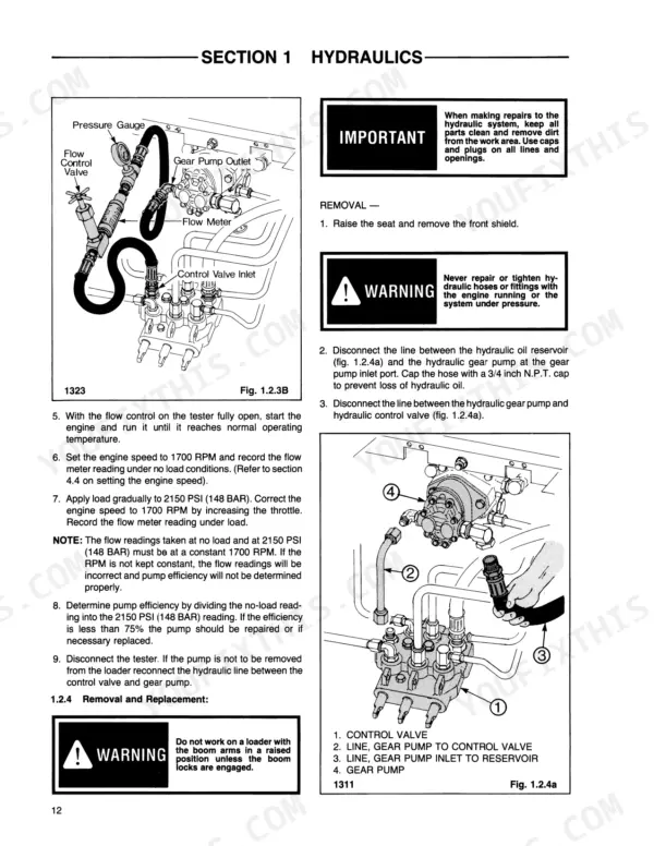
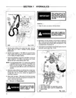
| Gear Pump | 12-17 | Specifications, Testing, Hydraulic Pump Flow, Removal, Replacement, Disassembly and Inspection, Start-Up After Repair |
| Control Valve | 18-27 | Specifications, Testing and Adjusting Relief Valve, Control Valve Removal Replacement, Disassembly and Inspection, Spool Seal Replacement |
| Hydraulic Cylinders | 28-36 | Specifications, General Information, Cylinder Removal, Cylinder Disassembly and Inspection |
| Oil Filter | 37 | Specifications, Filter Replacement |
| Oil Cooler | 38 | Specifications, Service |
| Oil Reservoir | 39-41 | Specifications, Checking and Adding Oil, Filter Replacement |
| Electrical | 161-202 | Wiring Diagrams, Instrumentation, Battery, Starting System, Charging System |
| Main Frame | 203-220 | Quick-Tach Assembly, Boom Arms, Operator Guard, Rear Door |
| Engine | 221-290 | Engine Removal, Engine Overhaul, Cooling System, Fuel System, Injection Pump, Injectors |
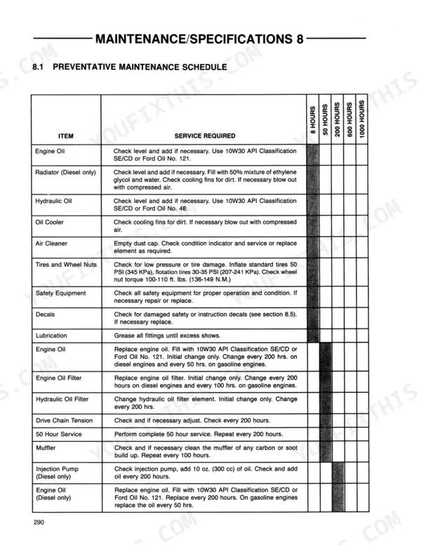
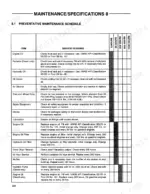
| Maintenance / Specifications | 291-306 | Preventative Maintenance Schedule, 50 Hour Service Check, Loader Specifications, Torque Specifications, Decals |
Quick Reference Specifications
| Specification | Value | Page |
|---|
| Compressed air pressure | 100 psi (6.9 bar) | p. 4 |
| Filtration | 10 Micron | p. 8 |
| Filtration, reservoir | Two, 100 micron elements | p. 8 |
| Rated Pressure | 2150 PSI (148 Bar) | p. 8 |
| Max. surge pressure | 4150 PSI (286 BAR) | p. 44 |
| Max. allowable case pressure | 25 PSI (1.7 BAR) | p. 46 |
| Foot pedal lock assembly positioning from inside of R.H. frame | 7.125 in. (181 mm) | p. 137 |
| Foot pedal shield stop clearance | 1 inch (25.4 mm) | p. 140 |
| Alternator Rating | 35A @ 14V | p. 161 |
| Rotor Coil Resistance at 68°F (20°C) | 3.9 ohm | p. 163 |
| Starter Current Draw (No Load) | 130 Amp. | p. 161 |
| Starter Armature Shaft Max. Runout | .002 in. (.05 mm) | p. 161 |