

A Ford 1110, 1210 repair manual PDF running 374 pages buys you one thing: the ability to finish any job on these compact diesel tractors without calling the dealer, using the same factory document (SE 4300 284) their techs read. Wiring diagrams trace each circuit from battery through glow plugs to the instrumentation, while hydraulic schematics map the flow from pump and filter out to the three-point hitch. Rebuild procedures cover both the 10 x 2 gear transmission and the hydrostatic drive, standard and mid-mount PTO, differential lock, brakes, and splitting the tractor at every joint. Set the injectors to pop at 1706 PSI, and torque the head bolts to spec on reassembly: 94.0-97.6 lbs.-ft. on the 1110, 32.5-36.2 lbs.-ft. on the 1210. Hay down and the tractor in two halves on the barn floor is no time to guess. Bought once, this bookmarked, keyword-searchable file is yours for as long as you keep the machine.
Other edition of this manual
What's Inside This Ford 1110, 1210 Repair Manual
| System | Pages | Key Topics |
|---|---|---|
| Service Manual | 1-2 | Title Page |
| Repair Manual | 3 | Title Page |
| Safety Precautions | 5 | Eye Protection, Breathing Protection, Hearing Protection |
| Service Techniques | 6-8 | Service Safety, Cleaning Fluids, O-Rings, Hoses, Tubes |
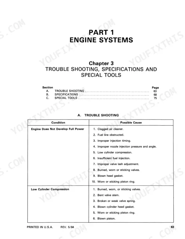
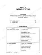
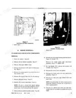
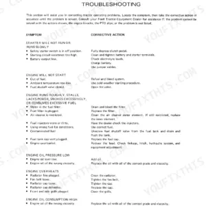
| Engine Systems | 9-86 | Engine and Lubrication System, Cooling Systems, Trouble Shooting, Specifications and Special Tools |
| Fuel System | 87-116 | Diesel Fuel System, Injectors |
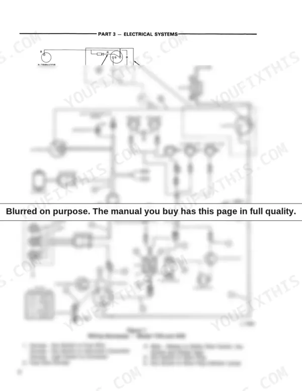
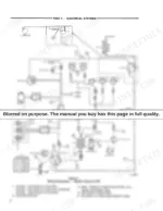
| Electrical Systems | 117-182 | Wiring, Switches, Glow Plugs and Instrumentation, Battery, Starting Systems, Charging System |
| Clutches | 183-194 | Single Clutches, Servicing Clutch Associated Components |
| Transmission Systems | 195-246 | Standard 10 X 2 Gear Transmission, Hydrostatic Transmission, Hydrostatic Transmission Gear Box |
| Power Take-Off | 247-266 | Standard Power Take-Off, Mid Mount Power Take-Off |
| Differential, Rear Axle and Brakes | 267-282 | Differential Assembly, Rear Axle, Brakes, Final Pinion, Differential Lock |
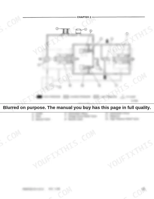
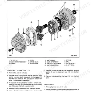
| Hydraulic System | 283-304 | Hydraulic System Circuits, Hydraulic Pump and Filter |
| Steering System | 305-316 | Steering Gear Assembly, Pitman Arm, Drag Link, Spindle Arms, Tie Rod |
| Front Axle | 317-344 | Two Wheel Drive, Four Wheel Drive |
| Wheels and Tires | 345-350 | Tread Setting, Liquid Ballast, Cast Iron Weight, Tire Inflation, Wheel Bolt Torque |
| Separating the Tractor | 351-374 | Front Axle, Engine, Transmission, Rear Axle Center Housing, Rear Axle Housing |
Quick Reference Specifications
| Specification | Value | Page |
|---|---|---|
| All Models | ||
| Connecting Rod Cap Bolts | 18-20 lbs.-ft. (24-27 Nm) | p. 85 |
| Camshaft Nut | 86.8-94 lbs.-ft. (117.6-127 Nm) | p. 85 |
| Crankshaft Main Bearing Holders | 18-22 lbs.-ft. (25-29 Nm) | p. 85 |
| Main Bearing Holder Retaining Bolt | 18-22 lbs.-ft. (25-29 Nm) | p. 85 |
| Injection Pressure | 1706 PSI (120 kg/cm²) | p. 114 |
| Spray Angle | 12° | p. 114 |
| Battery voltage | 12 volt | p. 129 |
| Capacity test discharge rate | 215 amp | p. 132 |
| Hydrostatic Control Rod length | 10.9 inch (278 mm) | p. 243 |
| Hydrostatic Transmission Cover Screws torque | 1.5-2.0 lbs.-ft. (2-2.5 Nm) | p. 246 |
| 1110 | ||
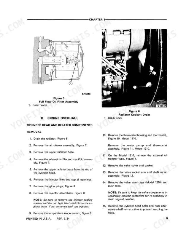
| Head Bolt Torque (Model 1110) | 94.0-97.6 lbs.-ft. | p. 25 |
| 1210 | ||
| Head Bolt Torque (Model 1210) | 32.5-36.2 lbs.-ft. | p. 25 |
Ford 1110, 1210 Common Problems This Manual Covers
Ford 1110 hydrostatic transmission suddenly stops driving, pedal feels loose with no response forward or reverse
Check the hydrostatic control linkage before condemning the transmission. Measure the control rod; correct length is 10.9 inches (278 mm) as shown on page 243, and adjust it if the pedal feels sloppy. Verify transmission oil level and inspect the linkage pivots for a slipped pin or loose jam nut before splitting the tractor.
Manual Section: Transmission Systems p. 243Engine cranks but will not start after fuel filter or sediment bowl service
Bleed air from the fuel system; that is the usual culprit after filter work. Open the bleed screws and work fuel through until it runs clear with no bubbles, following the diesel fuel system procedures starting on page 87. If it still will not fire, have the injectors pop tested; opening pressure is 1706 psi per page 107.
Manual Section: Fuel System p. 87Battery goes dead overnight, intermittent electrical power, tractor clicks but will not crank
Test the battery under load first: draw 215 amps for 15 seconds and the reading must hold above 9.6 volts, per the capacity test on page 132. If the battery passes, pull the negative cable and check for parasitic draw through the key switch and wiring, using the electrical procedures starting on page 117.
Manual Section: Electrical Systems p. 132Clutch pedal free play excessive, gears grind and hard to engage from a stop
Measure clutch pedal free play; spec is 0.8 to 1.2 inches, and the adjustment procedure sits on page 186. Adjust the linkage back into range before pulling anything apart. If gears still grind with free play correct, inspect the release bearing and pilot area following the clutch service coverage starting on page 183.
Manual Section: Clutches p. 186Three-point hitch will not lift implement or drops slowly with engine running
Check hydraulic oil level and the suction filter first. Test relief pressure; the main relief valve should hold 1850 psi as listed on page 302. If pressure comes up short, remove and clean the pump inlet filter following the hydraulic system procedures starting on page 283, then retest before hooking the implement back up.
Manual Section: Hydraulic System p. 302Frequently Asked Questions
What are the torque specifications for the Ford 1110 head bolts?
The head bolts for the Ford 1110 tractor should be torqued in stages to 94.0-97.6 lbs.-ft. (127.4-132.3 Nm). p. 25
What is the correct valve lash adjustment for the Ford 1110 and 1210 engines?
The valve lash for both the Ford 1110 and 1210 engines should be adjusted to a clearance of 0.008 inches (0.2 mm) while the engine is cold. p. 25
What is the recommended coolant capacity for the Ford 1110 and 1210 tractors?
The cooling system capacity for the Ford 1110 is 3.2 U.S. quarts (3.0 Liters), and for the Ford 1210 it is 2.45 U.S. quarts (2.3 Liters). p. 84
What is the specified torque for the Ford 1210 wheel lug nuts?
The front wheel bolts for the Ford 1210 should be torqued to 43-54 lbs.-ft. (6-7.5 Kgm), and the rear wheel bolts should be torqued to 69-87 lbs.-ft. (9.7-12.2 Kgm). p. 349
What is the injection pressure setting for the injectors on the Ford 1110 and 1210?
The injectors for both models are set to an opening pressure of 1706 psi (120 kg/cm²). p. 107
What exactly do I receive with this Ford 1110 Repair Manual?
A 374-page Repair Manual in searchable PDF format, available the moment you complete checkout. View on computer, tablet, or phone, with no shipping wait.
Does this Ford 1110 manual allow printing?
Yes. Print individual pages or full chapters for your own shop use, on letter or A4 paper.


Reviews
There are no reviews yet.