
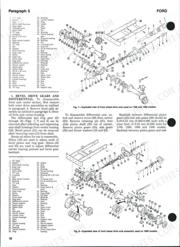
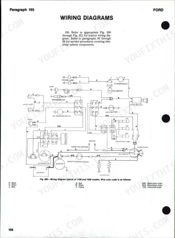
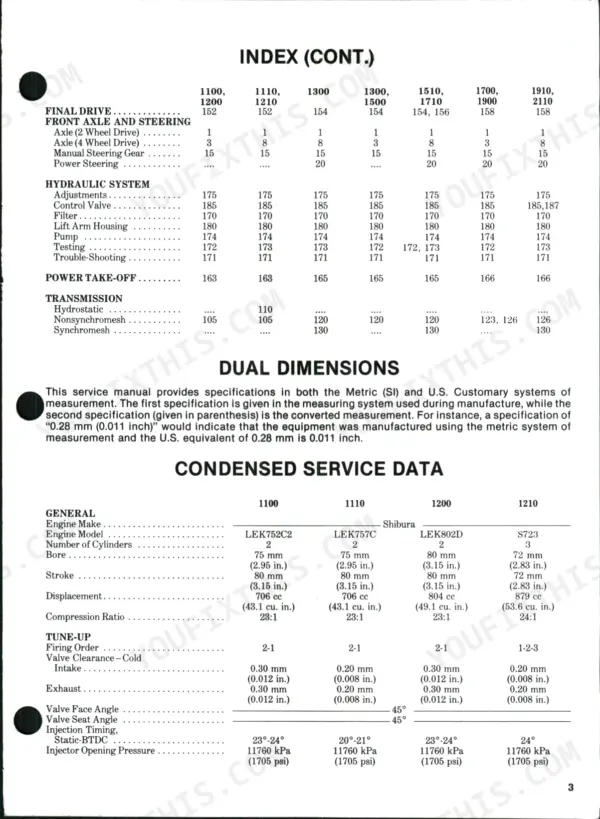
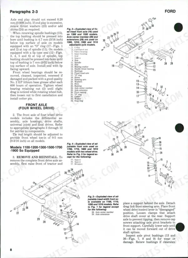
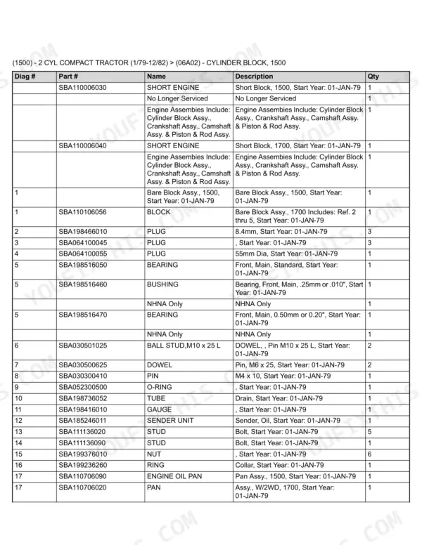
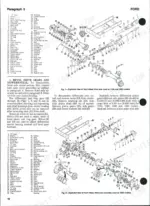
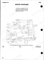
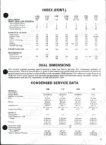
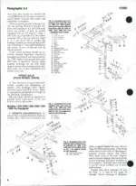
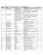
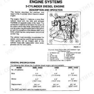
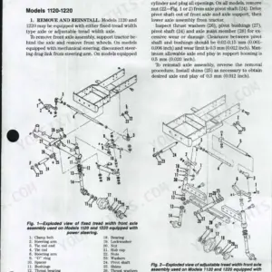
Hunting for a Ford 1910 shop manual PDF? This download is three factory books in one: the shop manual (pages 1-117), the illustrated parts catalog (118-347) and the operator's manual (348-404), covering the full 1979-1983 Ford compact tractor range from the 1100 to the 2110. Wiring diagrams sit on pages 106-117, tracing the fuse box, light switch, starter switch and glow plug circuits, and the diesel fuel section walks you through injection pump timing, spill timing and injector nozzle testing. Tractor split procedures handle the big jobs: clutch, differential and hydrostatic transmission overhauls. Set clutch pedal free travel to 20 to 30 mm, then check PTO clutch release bolt clearance at 0.9-1.0 mm on the 1310 through 2110 models. The parts catalog adds exploded views and part numbers for the same machines, so you can identify a component and order it without hunting for a second book. Your tractor predates the internet; forum guesses won't fix it. Bookmarked with a live text layer: search any spec, jump straight to the job, get wrenching.
Other editions of this manual
- Ford 1110, 1210 Repair Manual — Wiring Diagrams Original price was: $57.99.$39.99Current price is: $39.99.
- Ford 1910, 2110 Service Manual — Wiring Diagrams Original price was: $55.99.$39.99Current price is: $39.99.
- Ford 1710, 1510, 1310 Repair Manual — Wiring Diagrams Original price was: $59.99.$39.99Current price is: $39.99.
What's Inside This Ford 1100–2110 Manual
| System | Pages | Key Topics |
|---|---|---|
| Clutch & Transmission | Clutch, Engine Clutch, Standard Transmission, Hydrostatic Transmission, Non-Synchromesh Transmission, Transmission | |
| Fuel System | Diesel-Fuel System | |
| Cooling System | Radiator, Thermostat, Water Pump | |
| Engine | Lubrication & Maintenance | |
| Electrical System | Wiring Diagrams, Electrical Systems | |
| Rear Axle, Differential & Brakes | Final Drive, Brakes, Rear Axle | |
| Front Axle & Steering | Front Axle, Manual Steering Gear, Power Steering System, 2WD and 4WD Axle Assemblies | |
| Hydraulics & 3-Point Hitch | Hydraulic System, Hydraulic Systems | |
| Body & Operator Station | Instrument Panel, Seats | |
| Decals & Accessories | Decals, Safety & Instruction Decals | |
| Other Components | Service Data, Axle Center Housing, Sheet Metal, Wheels & Weights, Miscellaneous, General Infomation - Abbreviations, General Infomation - Metric to Inches, International Symbols, Safety Precautions, Controls & Instruments, Operation, Specifications, Pre Delivery & 50-Hour Service |
Quick Reference Specifications
| Specification | Value | Page |
|---|---|---|
| Clutch pedal free travel | 20 to 30 mm (3/4 to 1-1/16 inches) | p. 58 |
| Pto clutch release bolt clearance (1500, 1700, 1900 models) | 1.6-1.8 mm (0.063-0.070 inch) | p. 58 |
| Pinion clearance | 0.2-1.5 mm (0.008-0.060 inch) | p. 56 |
| Model 1210 Armature Shaft Runout | 0.08 mm (0.003 in.) | p. 56 |
| Rotor slip ring resistance (1100, 1110, 1200, 1210, 1310 models) | 4.2 ohms | p. 55 |
| Rotor slip ring resistance (1500, 1700, 1900 models) | 10.6 ohms | p. 55 |
Ford 1100–2110 Common Problems This Manual Covers
Ford 1710 cranks normally after fuel filter change or long storage but engine will not start
Check for air in the fuel system first. Open the bleed screws at the filter housing and injection pump, then crank until fuel runs solid with no bubbles, working from the tank to the filter to the high pressure lines. Replace the element with the correct part (13.2 mm I.D. mounting hole, page 147) and bleed again.
Manual Section: Bleeding p. 45Three point hitch will not lift, raises slowly, or drops with an implement attached
Check fluid level and condition first; milky or dark oil means change it along with the filter element. Test relief valve pressure with a gage in the lift circuit, then measure pump output against the 4.0 U.S. gpm (15.14 liters/min) capacity listed on page 392. Low flow with clean fluid points to a worn pump.
Manual Section: Testing p. 95Clutch slips under heavy load or gears grind every time the range lever is shifted
Measure clutch pedal free travel before splitting the tractor. Adjust the linkage until you have 20 to 30 mm (3/4 to 1-1/16 inches) of free play, the spec on page 58. If travel is correct and the clutch still slips, the disc is worn or oil soaked; split the tractor and inspect the pressure plate and release lever height.
Manual Section: Adjustment p. 58Starter solenoid clicks but engine cranks slowly or battery drains flat sitting overnight
Test the battery under load and clean both cable ends down to bright metal before condemning the starter. If cranking stays slow with a good battery, pull the starter and check pinion to thrust collar clearance, 0.2-1.5 mm (0.008-0.060 inch) per page 56, then inspect the brushes and commutator. Bench test the solenoid before reassembly.
Manual Section: Starter p. 56Charge warning light stays on and battery never comes up during field work
Check belt tension and battery connections first. Run the alternator output test at rated engine speed with a voltmeter across the battery; voltage stuck at battery level means no charge. Measure rotor slip ring resistance, which should be 4.2 ohms on 1100, 1110, 1200, 1210 and 1310 models per page 55, and replace the rotor if open or shorted.
Manual Section: Alternator p. 55Frequently Asked Questions
What are the cylinder head bolt torque specifications for a Ford 1500 tractor?
For the Ford 1500 tractor, the cylinder head retaining nuts and cap screws should be tightened in three steps to a specified torque of 150-155 N·m (111-114 ft.-lbs.). p. 27
What is the recommended valve clearance for a Ford 1510 tractor?
The recommended valve clearance for the Ford 1510 tractor is 0.20 mm (0.008 inch) for both intake and exhaust valves, measured with the engine cold. p. 27
How often should the engine oil and oil filter be changed on a Ford 1500 tractor?
The engine oil should be changed every 100 hours of operation, and the engine oil filter should be changed every 200 hours of operation. p. 373
What is the correct fuel injection pump timing for a Ford 1500 tractor?
The correct timing for the Ford 1500 tractor is 23°-24° BTDC, which corresponds to a dial indicator reading of 4.055-4.407 mm (0.160-0.174 inch). p. 47
How quickly can I access this Ford 1100 & variants manual after buying?
A 404-page Shop Manual in searchable PDF format, available the moment you complete checkout. View on computer, tablet, or phone, with no shipping wait.
Are there any print restrictions on this Ford 1100 & variants manual?
Yes, print as many copies as you want, and there are no restrictions. Many mechanics print the section they need and bring it to the shop floor.
Does this Ford 1100 & variants manual include wiring diagrams?
Yes. You'll find full electrical schematics with wire routing diagrams, connector identification, and circuit descriptions.



Reviews
There are no reviews yet.