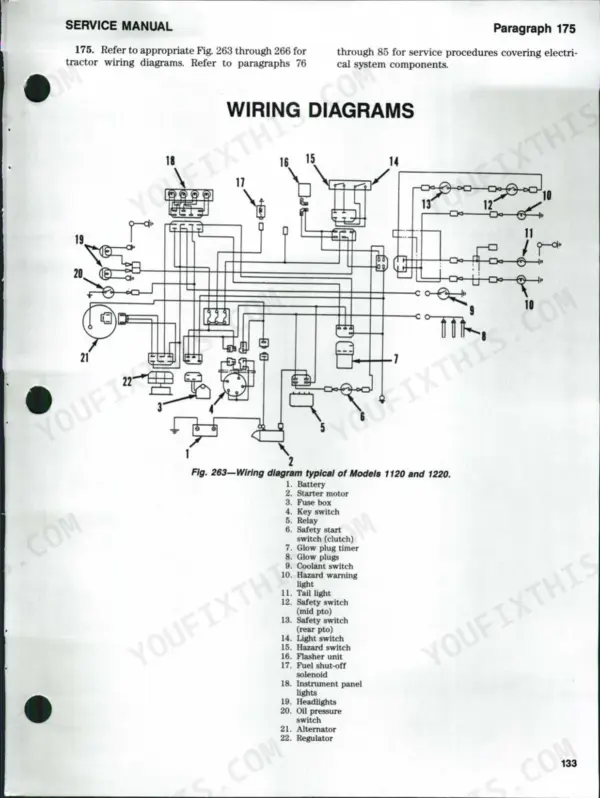
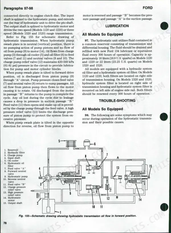
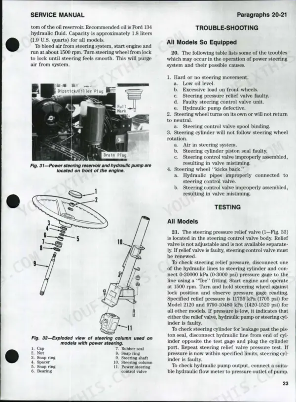
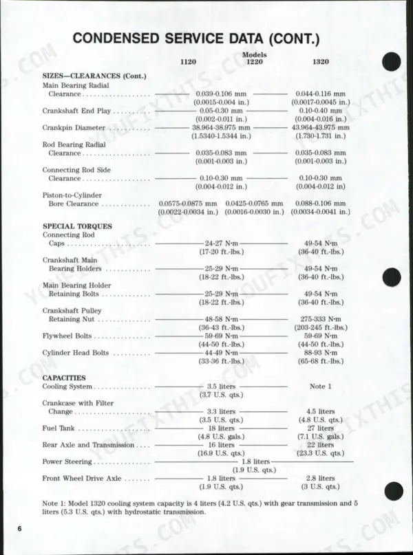
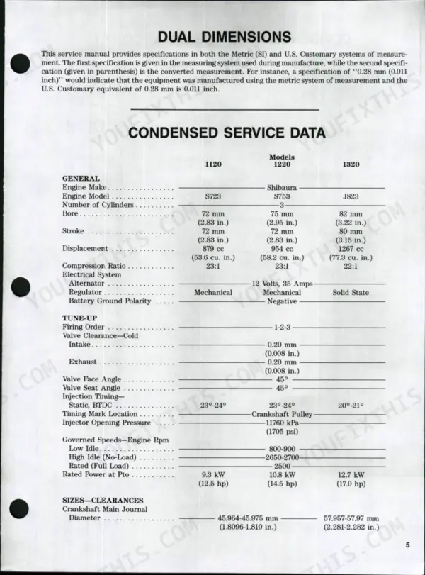


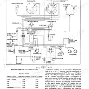
This 135-page Ford Shop Manual (models 1120, 1220, 1320, 1520, 1720, 1920, and 2120) puts the complete diesel fuel system, hydraulic lift, and transmission overhaul procedures in your hands for every gear configuration these tractors shipped with. You get full wiring diagrams for the alternator, glow plugs, and starter circuit, plus hydraulic schematics covering the flow control valve, lift control valve, and remote control valve. Troubleshooting charts walk you through hydraulic pressure faults and power steering complaints step by step, and the torque and clearance tables back every spec with real numbers. Check valve clearance during your next teardown and confirm coolant capacity before you button up the cooling system; these aren't estimates, they're the numbers Ford's own techs used. No more flipping through three forum threads to find one torque value. Bookmarked by section and searchable by keyword, so you can pull up the injection pump procedure on your phone before you even wipe your hands.
Complete the set for your 1120-2120
- Operator Manual: Ford 2120, AV413A, AV413P Tractor Operator Manual
- Operator Manual: Ford 1520 Tractor Operator Manual
- Operator Manual: Ford 1920 Tractor Operator Manual
Other editions of this manual
What's Inside This Ford 1120-2120 Manual
| System | Pages | Key Topics |
|---|---|---|
| Brakes | Adjustment, R&R and Overhaul, Pedal Free Travel, Brake Drum Inspection | |
| Clutch | Adjustment, Dual Plate Clutch, Single Plate Clutch, Tractor Split | |
| Cooling System | Radiator, Thermostat, Water Pump, Coolant Capacities | |
| Diesel Fuel System | Engine Speed Adjustment, Fuel Filter and Bleeding, Governor, Injection Pump, Injector Nozzles | |
| Differential and Bevel Drive Gears | Bevel Gears R&R, Differential R&R, Tractor Rear Split, Pinion Bearing Preload | |
| Electrical System | Alternator and Regulator, Engine Fuel Stop Solenoid, Glow Plugs, Safety Start Switches, Starting Motor and Solenoid | |
| Engine and Components | Assembly, R&R, Camshaft and Cam Followers, Connecting Rods and Bearings, Crankshaft and Bearings, Cylinder Head, Engine Balancer, Flywheel | |
| Front Axle (Two Wheel Drive) | Assembly R&R, Front Wheel Bearings, Spindles and Bushings, Tie Rods and Toe-In | |
| Front Wheel Drive Axle | Assembly R&R, Bevel Drive Gears, Differential, Final Drive and Wheel Hub, Lubrication, Transfer Case | |
| Hydraulic Lift System | Flow Control Valve, Check Valve and Safety Relief Valve, Fluid and Filter, Hitch Adjustments, Hydraulic Lift Housing, Hydraulic Pump, Lift Control Valve, Remote Control Valve | |
| Power Steering System | Lubrication and Bleeding, Steering Control Valve, Steering Cylinder, Steering Pump, Testing, Trouble-Shooting | |
| Power Take-Off | Standard Rear PTO, Mid-Mount PTO, R&R and Overhaul | |
| Transmission (9 X 3 Gear) | Assembly R&R, Lubrication, Overhaul, Mainshaft, Countershaft | |
| Transmission (12 X 4 Gear) | Assembly R&R, Lubrication, Overhaul, Mainshaft, Countershaft, Shift Forks and Rails | |
| Wiring Diagrams | Battery, Starter Motor, Alternator, Key Switch, Glow Plugs, Fuel Shut-Off Solenoid |
Quick Reference Specifications
| Specification | Value | Page |
|---|---|---|
| Hydraulic Lift System Testing | 154 | p. 3 |
| Injection Pump | 54 | p. 1 |
| Radiator | 70 | p. 1 |
| Thermostat | 71 | p. 1 |
| Water Pump | 72 | p. 1 |
| Hydraulic Lift System Trouble-Shooting | 153 | p. 3 |
| Cooling System | 3.5 liters (3.7 U.S. qts.) | p. 5 |
| gear to housing end clearance | 0.05-0.12 mm (0.002-0.0047 inch) | p. 49 |
| gear to housing end clearance (renew pump assembly if clearance exceeds) | 0.15 mm (0.006 inch) | p. 49 |
| delivery valve holders torque | 39-44 N·m (29-32 ft.-lbs.) | p. 52 |
| radiator cap pressure valve opening pressure | 90 kPa (13 psi) | p. 57 |
| thermostat start to open temperature | 71° C (160° F) | p. 57 |