
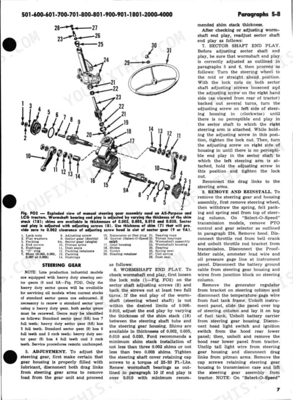
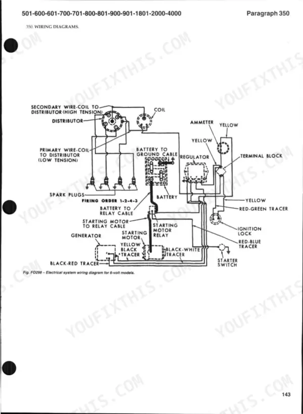
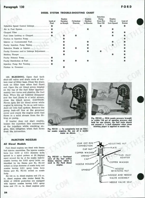
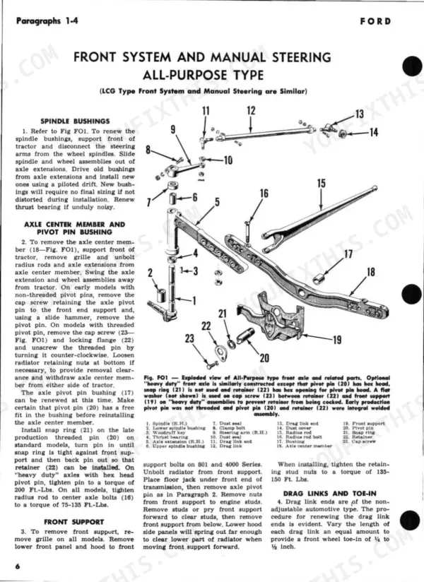
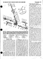
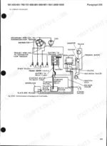
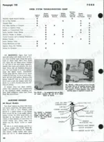
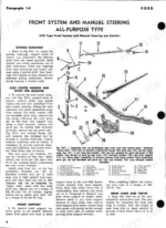
Looking for a Ford 2000 shop manual PDF that covers the whole family? This 144-page shop manual serves the 1955-1963 Ford 501, 600, 601, 700, 701, 800, 801, 900, 901, 1801, 2000, and 4000 tractors in one download. Inside you get factory wiring diagrams for both 6-volt and 12-volt systems, hydraulic lift schematics, Select-O-Speed transmission overhaul steps, and page after page of exploded views for the engine, clutch, differential, and steering gear. A troubleshooting section walks you through diesel fuel system quick checks and LP-gas faults. Torque the cylinder head cap screws to 65-70 ft.-lbs., set the injector mounting bolts at 15 ft.-lbs., and renew the fuel filter element every 400 hours. Your tractor outlived its dealer network; the factory data doesn't have to disappear with it. Bookmarked PDF, opens on any device: pull it up in the shop and start wrenching.
What's Inside This Ford 600-4000 Series Manual
| System | Pages | Key Topics |
|---|---|---|
| Engine | - | Assembly R&R, Camshaft, Carburetor, Idle Adjusting Needle, Main Adjusting Needle, Diesel Fuel System, Filters, Bleeding, Governor, Non-Diesel Governor, Speed Adjustment, Cooling System, Pump R&R, Radiator, Lp Gas System, Filter |
| Ignition, Electrical and Wiring | - | Ignition & Electrical System, Generator and Regulator, Starting Motor, Wiring Diagrams, 6-Volt Electrical System, 12-Volt Electrical System |
| Clutch and Transmissions | - | Clutch, Adjustment, Release Bearing, Transmission (4-Speed), Assembly R&R, Clutch Shaft, Transmission (5-Speed), Transmission (Combination), Cluster Shaft, Transmission (Reversing), Input Shaft Housing, Shifter Cap Assembly, Transmission - "Select-O-Speed", Planetary Gear Power Flow, Hydraulic Circuits |
| Rear Axle, Differential and Final Drive | - | Rear Axle, Bearing Renewal, Shaft R&R, Differential, Overhaul, Remove and Reinstall, Final Drive, Axle Housings, Bevel Pinion, Brakes, Adjustment, Shoes, Belt Pulley, Pulley Shaft, Oil Seal, Power Take Off, Countershaft, Input Shaft |
| Front Axle and Steering | - | Front Axle, Axle Main Member, Drag Links and Toe-In, Front System, Spindle Bushings, Axle Center Member and Pivot Pin Bushing, Steering Gear, Adjustment, Wormshaft End Play, Power Steering System - All-Purpose, Lcg, And Utility Industrial, Lubrication, Bleeding, Power Steering System - Heavy Duty Industrial, Power Steering System - Row Crop Type, Control Valve, Power Cylinder Assembly, Power Steering Pumps - Hollow Plunger and Rotor Types, Pump Removal, Pump Overhaul, Power Steering Pumps - Roller Vane Type |
| Hydraulics | - | Hydraulic Lift System, Back Pressure Valve, Constant Draft Control, Hydraulic Power Package, Reservoir and Lines, Hydraulic Pump, Remote Control Valves, Adjustment, Control Lever |
| Service Data | - | General, Tune-Up |
Quick Reference Specifications
| Specification | Value | Page |
|---|---|---|
| Spark Plug Model (Gasoline) | AL7T | p. 5 |
| Spark Plug Model (LP-Gas) | ATL3A | p. 5 |
| cylinder head retaining cap screws torque | 65-70 Ft.-Lbs. | p. 39 |
| fuel filter element renewal interval | 400 hours or every six months | p. 53 |
| injector mounting bolt torque | 15 Ft.-Lbs. | p. 56 |
| Breaker contact gap | 0.024-0.026 inches | p. 64 |
| Breaker arm spring tension | 17-20 ounces | p. 64 |
| differential case bolts torque | 90-100 Ft.-Lbs. | p. 117 |
| wheel axle bearing retaining nuts torque | 130-150 Ft.-Lbs. | p. 119 |
| lift cover retaining cap screws torque | 45-65 Ft.-Lbs. | p. 126 |
| cylinder retaining cap screws torque | 60-80 Ft.-Lbs. | p. 127 |
| Engine Low Idle RPM | 475 RPM | p. 5 |
Ford 600-4000 Series Common Problems This Manual Covers
Ford 601 diesel cranks strong but will not start, or fires briefly and dies
Drain the sediment bowl and check for water or debris, then confirm the tank vent is clear and fuel flows freely to the filter. Replace the filter element if overdue; the disposable element is due every 400 hours or six months, covered on page 53. Bleed the system, then work the diesel troubleshooting chart.
Manual Section: Diesel Fuel SystemGas engine cranks fine but spark is weak, misfires, or dies intermittently
Pull the distributor cap and inspect the points for pitting and oil. Set the breaker contact gap to 0.024-0.026 inch and check breaker arm spring tension at 17-20 ounces, both on page 64. Clean or replace the spark plugs and tighten them to 24-30 ft-lbs. Test coil output before blaming the carburetor.
Manual Section: Ignition & Electrical System p. 64Three-point hitch lifts slowly, bobs under load, or will not raise an implement
Check the fluid level and condition first; milky or thin oil will kill pump prime. Verify the pump primes and holds pressure, then inspect the back pressure valve and control valve linkage for wear. If you pull the lift cover for repairs, torque the retaining cap screws to 45-65 ft-lbs on page 126 during reassembly.
Manual Section: Hydraulic Lift System p. 126Engine runs hot, loses coolant slowly, and shows seepage along the cylinder head
Clean the radiator core and chaff screen, top off the coolant, and pressure test the system before condemning the head gasket. Inspect hoses and the thermostat for restriction. If the head comes off, check it for warpage and tighten the retaining cap screws in sequence to 65-70 ft-lbs, shown on page 39.
Manual Section: Engine p. 39Diesel smokes black, surges at steady throttle, and lacks power under load
Run the quick checks for surging and uneven cylinders before touching the injection pump. Check for restricted filters and air leaks on the suction side of the system. If an injector tests bad, service or replace it and torque the mounting bolts evenly to 15 ft-lbs, per page 56.
Manual Section: Diesel Fuel System p. 56Frequently Asked Questions
What are the torque specifications for the cylinder head bolts on the Ford 501, 600, 601, 700, 701, 800, 801, 900, 901, 1801, 2000, and 4000 series tractors?
For non-diesel engines, the cylinder head bolts should be tightened in the specified sequence to a torque of 65-70 Ft.-Lbs. For diesel models, the cylinder head bolts must be tightened to a torque of 100-105 Ft.-Lbs. p. 39
How do I reset or adjust the Select-O-Speed transmission bands?
Band adjustments must be performed with the transmission at operating temperature. For Band 1, tighten the adjusting screw to 10 Ft.-Lbs., then back it out exactly one full turn. For Bands 2 and 3, tighten the adjusting screw to 5-10 Ft.-Lbs. with the engine running at 800 RPM, then back out the screw exactly 3/4-turn. p. 86
What is the correct valve tappet gap for Ford tractors?
The valve tappet gap for both intake and exhaust valves should be set to 0.015 inches when the engine is at normal operating temperature. p. 39
What is the required hydraulic system operating pressure for the Ford hydraulic lift system?
The hydraulic lift system operating pressure should be 1,950-2,050 psi. This is checked by attaching a 3,000 psi gage into a tee in the lift cylinder cross-over line. p. 141
What is the recommended engine oil capacity for the cooling system on the 600 and 700 series tractors?
The cooling system capacity for the 600 and 700 series tractors is 3.75 gallons. p. 5
How is this Ford 501 Shop Manual delivered?
Immediate download of the complete 144-page searchable Shop Manual. Access it on any device, from a laptop at your desk to a phone in the field.
Is printing allowed for this Ford 501 Shop Manual?
Print away. There is no DRM and no page limit. Many buyers print one chapter at a time and leave the rest on a tablet.


Reviews
There are no reviews yet.