Hyster E1.25XL-E5.50XL, J2.00-3.00XL Series Service Manual with Wiring Diagrams

$39.99 USD · one-time payment

Model: E1.25XL | E1.50XL | E1.75XL | E2.00-2.50XL | E2.00-3.00XL | E3.50-4.00XL | E5.00XL | E5.50XL | J2.00-2.50XL | J2.00-3.00XL
Type: Electric Lift Trucks
722 Pages·45 MB·Searchable PDF·English·Print-Ready
  • ✓ Wiring Diagrams
  • ✓ Hydraulic Schematics
  • ✓ Torque Specs
  • ✓ Multi-Level Bookmarks (3-level navigation)
Preview Sample Pages (PDF)
Add to Cart
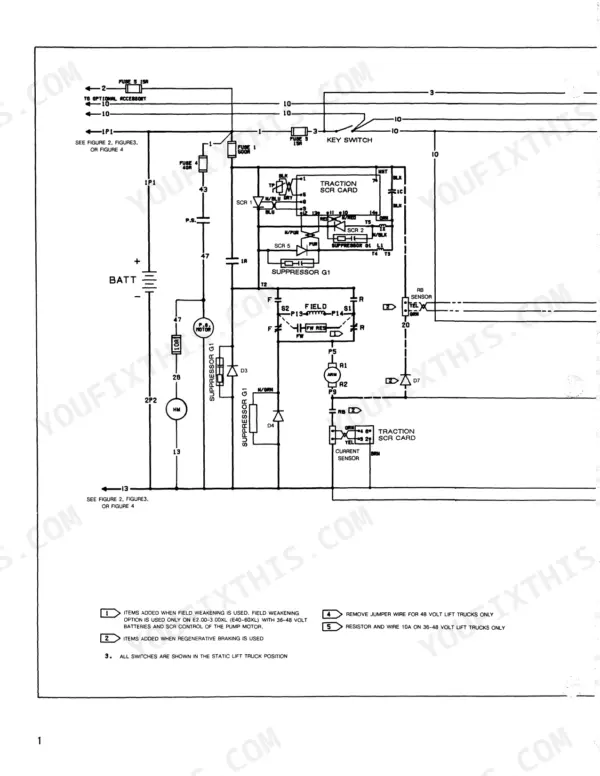
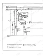
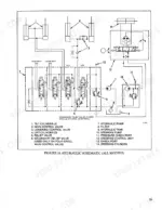
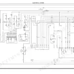
Hyster E1.25XL-J3.00XL wiring diagram showing traction SCR card, battery, pump motor, fuses, and field weakening components.
Hyster E1.25XL-E5.50XL, J2.00-3.00XL Series Service Manual with Wiring Diagrams
$39.99

Instant Download 24/7

  • Works on PC, Mac, tablet, and phone.
  • Download once, keep forever


Guaranteed Safe Checkout
Visa Mastercard PayPal Apple Pay Google Pay

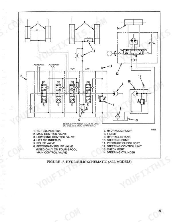
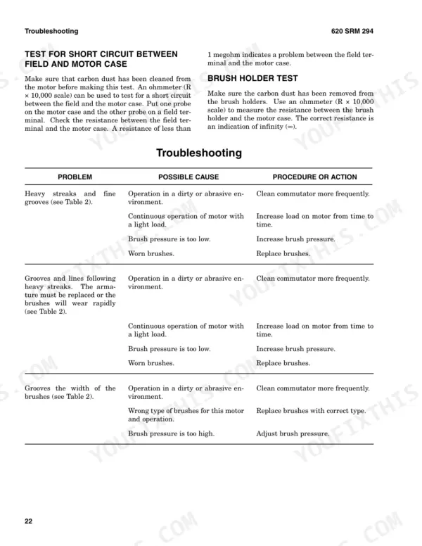
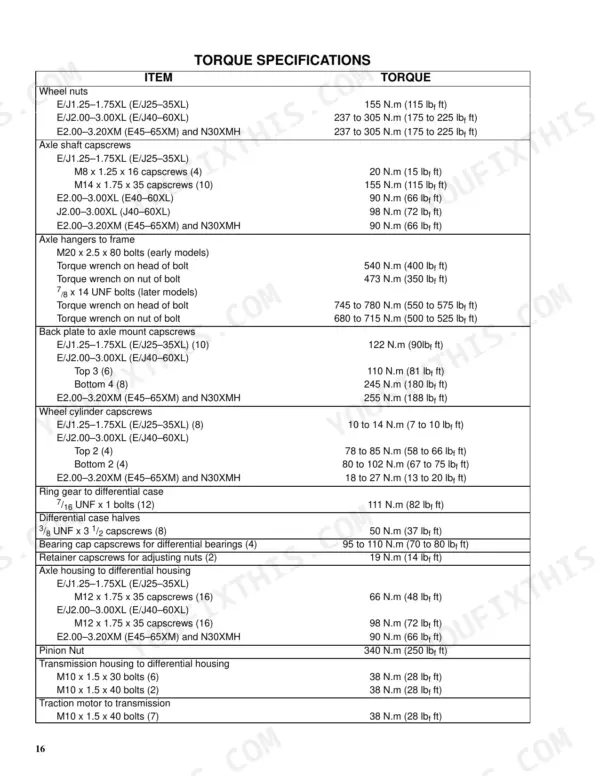
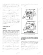
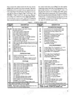
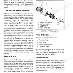
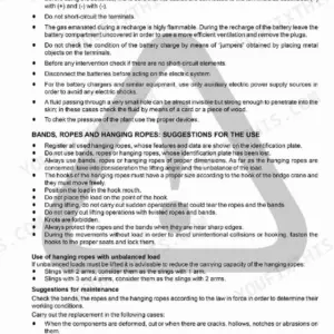
Hyster issued this 722-page service manual under its own document number, 620 SRM 294, for ten XL electric lift truck variants, E and J models from the E1.25XL to the E5.50XL. Wiring diagrams in this Hyster E1.25XL service manual PDF trace the EV-100 motor controller and its SCR control, while the hydraulic schematic maps the main control valve and solenoid valve circuit. Drive axle, differential, steering control unit and tilt cylinder repairs sit beside the DC motor work: brush replacement, stoning the commutator, and armature and field coil tests for open and short circuits. Torque GE motor power cables at M8 terminals to 18 to 22 Nm (159 to 195 lbf in), and bring the rear overhead guard fasteners on E1.25-3.00XL trucks to 435 Nm (320 lbf ft). Due for a brush and commutator inspection? Compare your commutator against the normal surface and commutator problems guidance. Pay once, and the bookmarked, text-searchable PDF stays yours for your trucks.

What's Inside This Manual

SystemPagesKey Topics
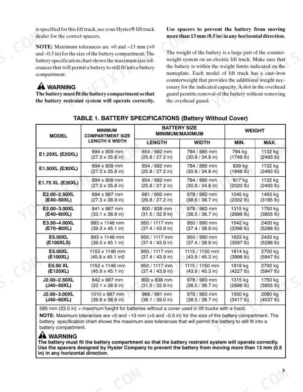
General1Hydraulic Pump Motor and Traction Motor
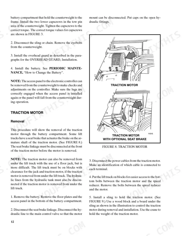
Brush and Commutator Inspection1-7Hydraulic Pump Motor and Traction Motor, Steering Pump Motor, Normal Commutator Surface, Commutator Problems
Brush Replacement8-9Motor Brushes, Brush Springs, Brush Holders, Terminal Mounts
Stoning the Commutator10-11Commutator, Brush Seater Stone, Key Switch, Seat Switch, Battery
Motors Repair12-19Disassemble (Traction Motor and Hydraulic Pump Motor, Steering Pump Motor), Assemble (Traction Motor and Hydraulic Pump Motor
Brush Alignment, Traction and Hydraulic Motors20Brush Holder, Commutator, End Frame, Brush Mounting Plate
Tests for Damaged Field and Armature20-21Test for an Open Circuit in Armature, Test for Short Circuit in One Armature Winding, Test for Short Circuit to Armature Shaft, Test for Open Circuit in Field Coil
DC Motor Maintenance22-51Brush Inspection, Commutator Maintenance, Motor Disassembly, Motor Assembly, Troubleshooting
Drive Axle and Differential52-67Drive Axle Removal, Differential Disassembly, Pinion Assembly, Torque Specifications, Troubleshooting
Steering Control Unit68-122Steering Control Unit Description, Seat Brake Assembly, Brake System Repairs, Troubleshooting, Torque Specifications
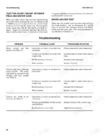
Hydraulic System123-148Hydraulic Schematic, Main Control Valve, Relief Valve Adjustments, Solenoid Valve, Troubleshooting
Tilt Cylinders149-188Tilt Cylinder Repair, Leak Checks, Troubleshooting, Meter Specifications, Battery Indicator Troubleshooting
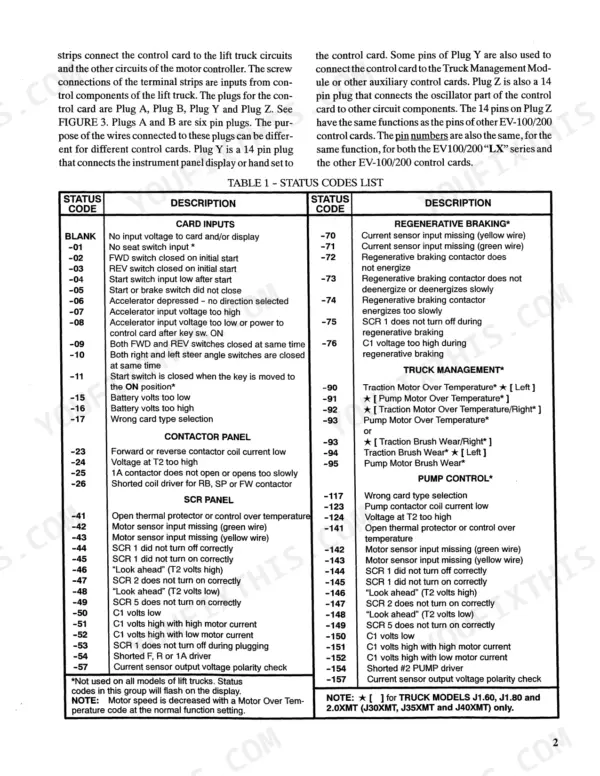
Controller Description and Operation189-228Motor Controller Operation, SCR Control, Troubleshooting Fault Codes, Wiring Diagrams, Battery Maintenance
Controller Repairs and Adjustments229-256Control Card Adjustments, General Electrical System Adjustments, Shunt and Ammeter, Fuses, Component Locations
Controller Troubleshooting257-386SCR Control Card, Status Code Description, Troubleshooting, Function 2 Creep Speed, Regenerative Braking
SitDrive Electric Lift Trucks387-539Ev-100 Motor Controller Adjustments, Electrical Checks and Adjustments, Check the Accelerator Card, Armature Shunt Method, Electrolyte
Vista Mast Description540-650Vista Mast, Upright Speeds, Lift Cylinders, Carriage, Torque Specifications
Diagrams651-694Schematic Diagram, Battery Indicator, SCR Control Card, Wire Diagram, Steering Column
Electrical Diagrams695-722Pump Motor SCR Control Schematic, Battery Indicator W/Lift Interrupt, Field Weakening and SCR Pump Wiring Diagram, Power Steering

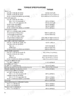
Quick Reference Specifications

SpecificationValuePage
E1.25-3.00XL (E/J25-60XL)
Overhead Guard Front Torque86 Nm (64 lbf ft)p. 7
Overhead Guard Rear Torque435 Nm (320 lbf ft)p. 7
All Models
Torque for capscrews fastening the pump to the motor48 Nm (35 lbf ft)p. 128
Torque for power cables at M8 or 5/16-inch terminals on General Electric motors18 to 22 Nm (159 to 195 lbf in)p. 126
Diode D3 and D4 tightening torque3.4 N.m (30 lbf in)p. 245
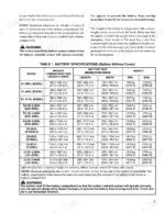
Battery temperature rise limit14°C (25°F) during an eight hour charging periodp. 434
Traction Motor to Transmission Bolt Torque38 N.m (28 lbf ft)p. 67
Pinion Nut Torque340 N.m (250 lbf ft)p. 67
Steer Axle Mount Bracket Hardware Torque88 N.m (65 lbf ft)p. 100
E20-30B/BS/BH
E20-30B/BS/BH Traction Fuse225Ap. 239
E20-30B/BS/BH Hyd. pump Fuse175Ap. 239
E/J1.25–1.75XL (E25–35XL)
Torque – Wheel Nuts, Drive Tires155 N.m (115 lbf ft)p. 641
BrandHyster
ModelE1.25XL, E1.50XL, E1.75XL, E2.00-2.50XL, E2.00-3.00XL, E3.50-4.00XL, E5.00XL, E5.50XL, J2.00-2.50XL, J2.00-3.00XL
Machine TypeElectric Lift Trucks
Manual TypeService Manual
LanguageEnglish
FormatSearchable PDF (Digital Download)
Pages722
File Size45 MB
Manual No.620 SRM 294
Wiring DiagramsYes
Hydraulic SchematicsYes
Torque SpecificationsYes
Bookmarked / IndexedYes