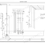
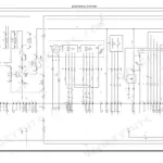
Adjusting the electromagnetic brake on a pallet truck is a job you follow page by page in this 185-page Hyster P1.6 service manual PDF, OEM ID 4138678, which covers four pedestrian tiller operated pallet truck models from P1.6 to P2.2. Wiring diagrams lay out the electrical system, and the same chapter handles the tiller board and module replacement; hydraulic diagrams show the circuit through the pressure regulating valves, cartridge solenoid valves, pressure relief valve and lift pump. The mechanics section deals with the traction wheel, castor wheels, load wheels, tiller and traction motor, and routine maintenance lists oils, lubricants and scheduled service. Fit a 175 A power fuse. Torque the traction wheel retaining nuts to 120 Nm. When your truck throws a DTC code, combi controller alarm or tiller board alarm, the diagnostics chapter covers module connectors and the monitor menu for tracing it. Buy it once; the bookmarked, text-searchable PDF stays yours for this truck.
What's Inside This Manual
| System | Pages | Key Topics |
|---|
| Technical Information | 1 | Hyster Service Centres, Specialized Technicians, Hyster Service Network |
| Introduction | 2-3 | Service Manuals, Maintenance Guidelines, Safety Rules, Suspension Elements |
| General Safety Rules | 4-12 | Personal Protective Equipment, Workplace Safety, Battery Safety, Suspension Elements, Maintenance Tips |
| Presentation | 13-22 | Truck Presentation, Views of the Truck, Truck Identification Data and Load Capacities (Truck Identification Data Plate, Mast Serial Number Stamp), Location of Documentation |
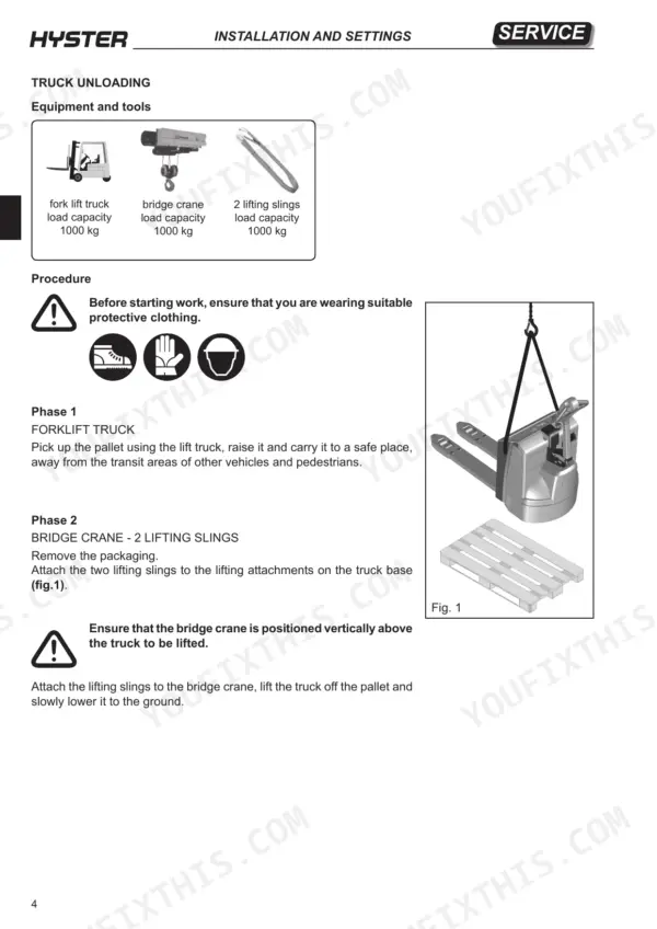
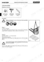
| Installation and Settings | 23-32 | Truck Unloading, Oil Reservoir, Battery Installation, Battery Cable Connection, Truck Use Conditions |
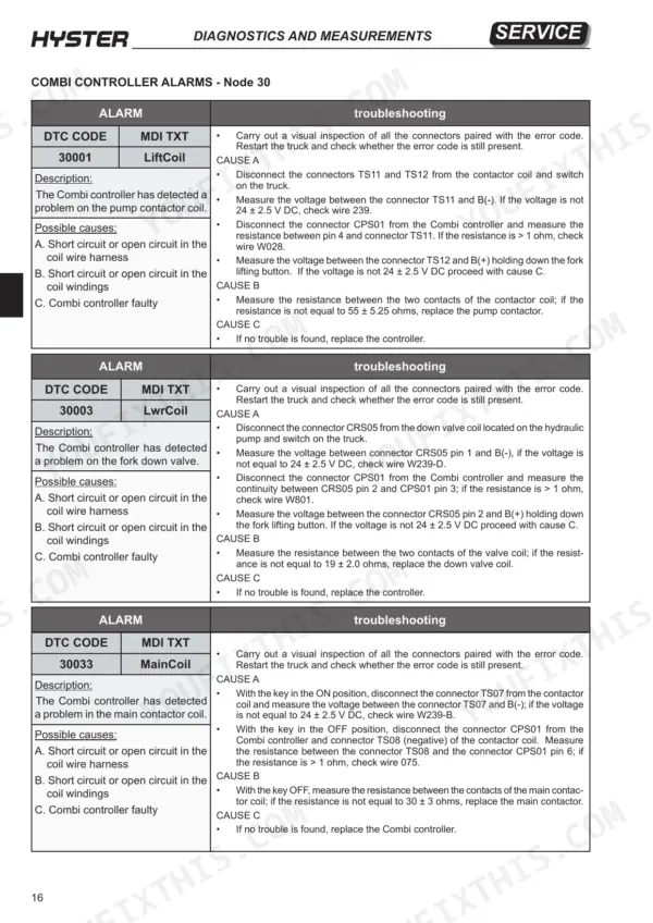
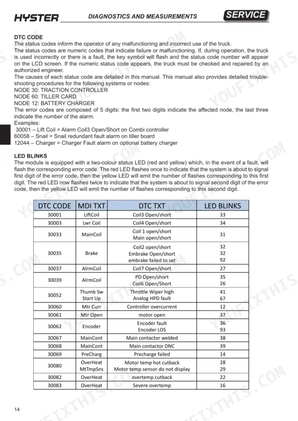
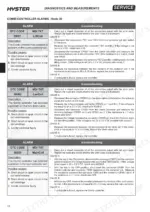
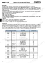
| Diagnostics and Measurements | 33-60 | Module Connectors, Combi Module, Monitor Menu, DTC Codes, Combi Controller Alarms, Tiller Board Alarms |
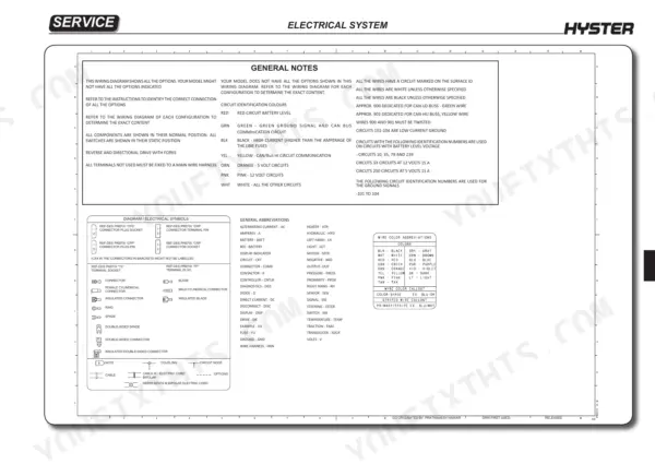
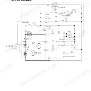
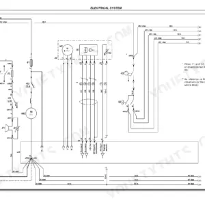
| Electrical System | 61-110 | Wiring Diagrams, Electrical Components, Tiller Board, Battery Charge Level Indicator, Configuration Parameters, Module Replacement |
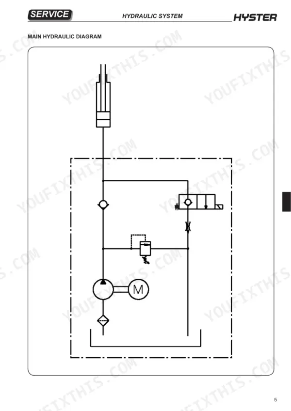
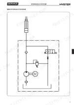
| Hydraulic System | 111-138 | Pressure Regulating Valves, Directional Valves, Hydraulic Diagrams, Pressure Relief Valve, Cartridge Solenoid Valves, Lift Pump |
| Mechanics | 139-165 | Traction Wheel, Castor Wheels Assembly, Load Wheels, Linkage, Tiller, Traction Motor |
| Reducer | 166-170 | Reduction Unit Components, Reduction Unit Removal, Reduction Gear Bearing |
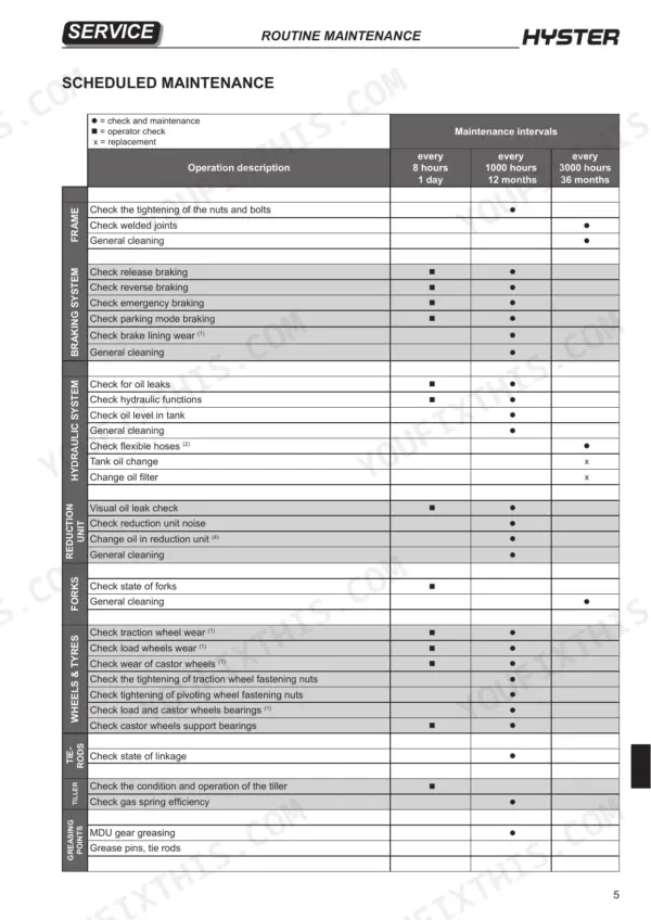
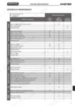
| Routine Maintenance | 171-179 | Oils and Lubricants, Cleaning Products, Scheduled Maintenance |
| Braking System | 180-185 | Electromagnetic Brake Components, Braking System Operation, Electromagnetic Brake Dismantling, Electromagnetic Brake Adjustment |
Quick Reference Specifications
| Specification | Value | Page |
|---|
| All Models |
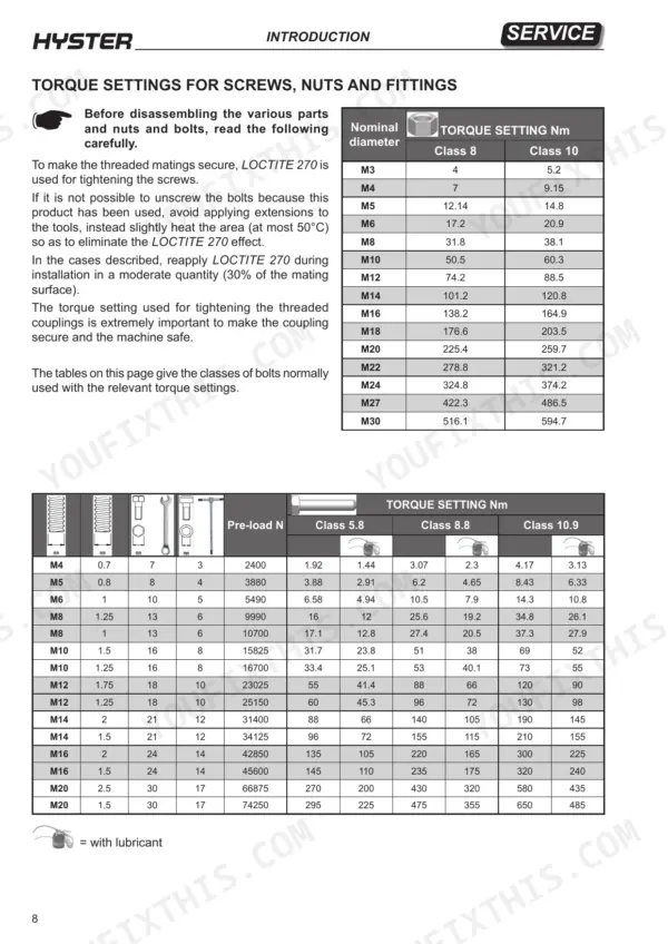
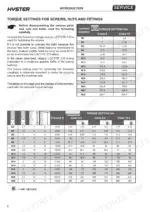
| M3 Class 8 Torque | 4 Nm | p. 8 |
| M3 Class 10 Torque | 5.2 Nm | p. 8 |
| Traction wheel retaining nuts torque | 120 Nm | p. 141 |
| Valve installation torque | 15 Nm | p. 121 |
| Power fuse | 175 A | p. 68 |
| Voltage | 24V | p. 35 |
| Fuse rating | 4A | p. 103 |
| Power fuse rating | 175A | p. 103 |
| Valve pressure setting adjustment | approx. 35/40 bar for each screw turn | p. 122 |
| Traction wheel fastening nut torque | 120 Nm | p. 141 |
| P1.6, P1.8 |
| Unladen weight (P1.6, P1.8) | 545 kg | p. 19 |
| P2.0, P2.2 |
| Unladen weight (P2.0, P2.2) | 632 kg | p. 21 |