
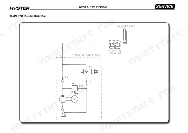
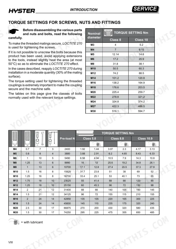
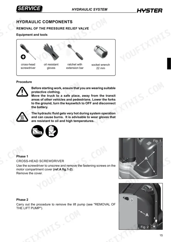
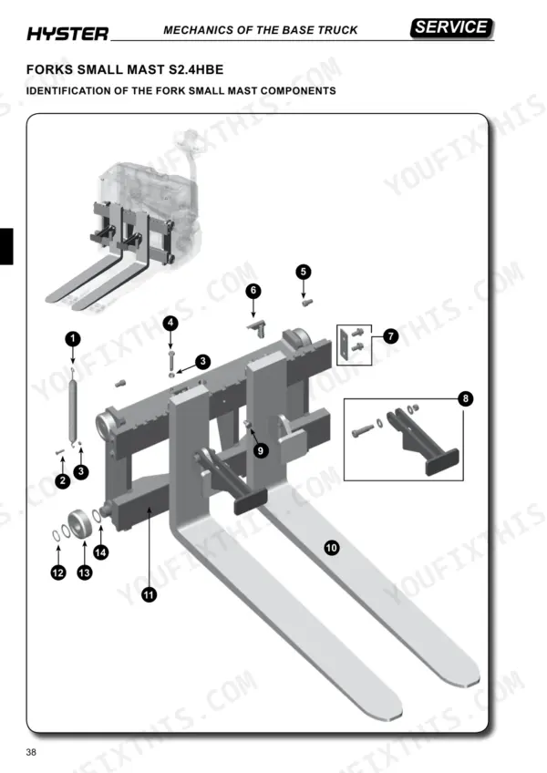
Written for the Hyster S2.4HBE stacker truck, OEM ID 1619008, this 68-page Hyster S2.4HBE service manual PDF covers one specific machine, so you know before buying that it fits. Hydraulic diagrams anchor the book. Around them sits coverage of the cartridge solenoid valves, lift cylinder and lift pump. The remaining chapters run through truck presentation and general specifications, MPB control parameter configuration for the electrical system, forks, small mast and load wheels on the base truck, then oils, lubricants and the scheduled maintenance plan. Keep compressed air at or below 1 bar when cleaning parts, and bring the seal carrier bush to 400 Nm on reassembly. If your job is tracing the lift circuit from the pump through the solenoid valves to the cylinder, the hydraulic schematics lay out that routing. Download it, jump to the Hydraulic System chapter with the bookmarks, and refit the solenoid valve screws at the 25 Nm the factory specifies.
What's Inside This Hyster S2.4HBE Manual
| System | Pages | Key Topics |
|---|---|---|
| Presentation | 13-18 | Truck Presentation, General Specifications |
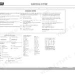
| Electrical System | 19-22 | MPB Control Parameters Configuration |
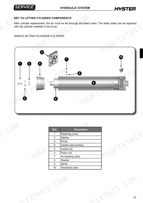
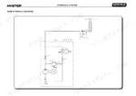
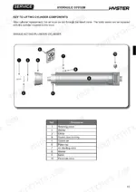
| Hydraulic System | 23-48 | Hydraulic Diagrams, Hydraulic Components, Cartridge Solenoid Valves, Cylinder, Lift Pump |
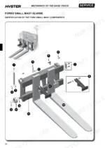
| Mechanics of the Base Truck | 49-60 | Forks Small Mast, Load Wheels |
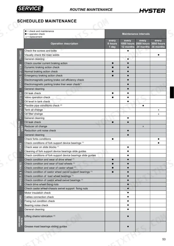
| Routine Maintenance | 61-68 | Warnings, Oils and Lubricants, Scheduled Maintenance |
Quick Reference Specifications
| Specification | Value | Page |
|---|---|---|
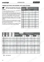
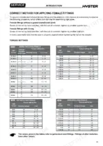
| Maximum air pressure for cleaning parts | 1 bar | p. 4 |
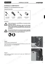
| Pressure relief valve installation torque | 12 Nm | p. 16 |
| Solenoid valve fastening screws torque | 25 Nm | p. 32 |
| Air bleeding valve screw torque | 10 Nm | p. 38 |
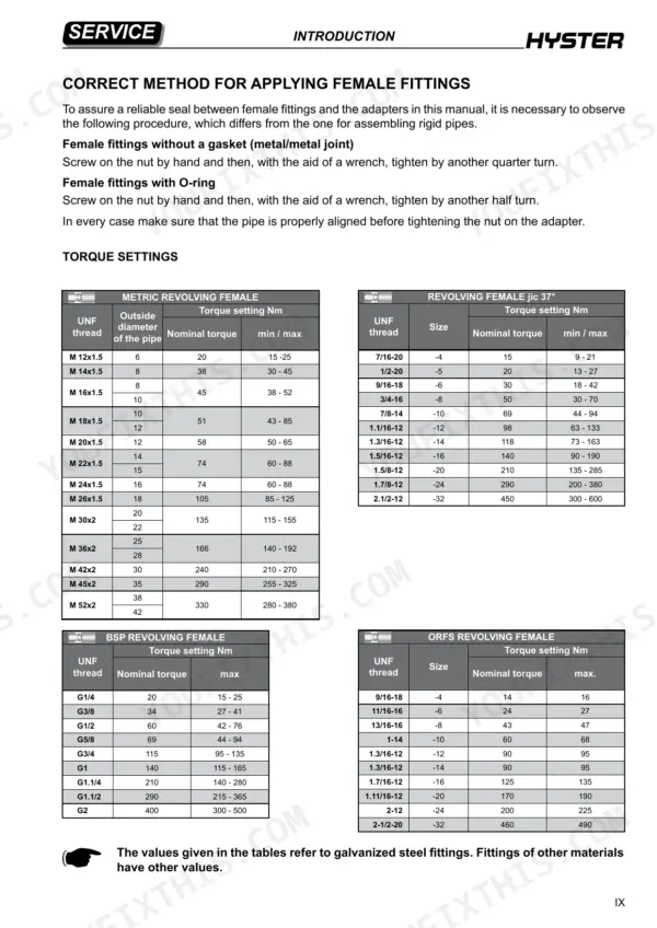
| Seal carrier bush tightening torque | 400 Nm | p. 40 |
| Maximum air pressure for cleaning | 1 bar | p. 4 |
| Rated capacity | 2400 kg | p. 17 |
| Battery voltage/capacity | 24 V / 150 Ah | p. 17 |
| Pressure relief valve tightening torque | 12 Nm | p. 28 |
| Solenoid valve fastening torque | 25 Nm | p. 32 |
| One-way valve tightening torque | 25 Nm | p. 33 |
| Lifting cylinder air bleeding screw torque | 10 Nm | p. 38 |
Hyster S2.4HBE Common Problems This Manual Covers
Hyster S2.4HBE one-way valve dirty or broken, raised forks will not stay in position
Lower the forks to the ground, turn the keyswitch OFF and disconnect the battery. Never work under a raised carriage, and eliminate residual hydraulic pressure first (page 63). Wear oil and heat resistant gloves because the fluid runs hot. Remove the lift pump, then unscrew the valve assembly with a 22 mm socket following page 33. Clean or replace it and torque to 25 Nm.
Manual Section: Dismantling of the One-Way Valve p. 33Lift cylinder static seals leaking hydraulic oil past the gaskets at the seal carrier bush
Lower the forks, eliminate residual hydraulic pressure (page 63) and wear oil resistant gloves because the fluid gets hot. Remove the fork as referenced on page 39, then unscrew the seal carrier bush with the section spanner. Pry out the gaskets and replace the entire kit. Clean the bush, lubricate the seals and contact faces with clean hydraulic oil, and torque the bush to 400 Nm per page 40.
Manual Section: Replacement of the Static Seals p. 39Lifting cylinder holding trapped air after cylinder removal or static seal replacement
Lower the forks and wear oil resistant gloves, since the hydraulic fluid gets hot enough to burn. Loosen the air bleeding valve with a 3 mm T handle hex spanner, connect the battery and turn the key ON. Lift with the tiller button until oil pours from the bleed valve, stop, and tighten the screw to 10 Nm following page 38. Wipe the cylinder with a clean cloth.
Manual Section: Lifting Cylinder: Air Bleeding p. 38Pressure relief valve setting too low to handle the pressure surge during initial lifting stage
Calibrate after any relief valve or hydraulic control unit replacement. Install the valve at 12 Nm (page 28), then load the forks to dataplate capacity. Loosen the lock nut, back the adjusting screw out until lifting stops, turn it in until the forks lift again, then add 1/4 turn per page 29. Trial lift, add another 1/4 turn if needed, and lock the nut. Never work under a raised carriage (page 63).
Manual Section: Calibration of the Pressure Relief Valve p. 29COMBI MPB module parameters changed from factory defaults, lift and travel speeds off setting
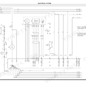
Check each COMBI MPB parameter against the default table on page 21: FORK LIFT SPEED 9, MAX SPEED FORW 9, MAX SPEED BACK 9, CREEP SPEED 2. Restore factory settings where possible, and never change any parameter if it jeopardizes truck safety. Access the menus using COMBI MPB manual P/N 1533762; wiring diagrams are in Service Manual B440 P/N 1619008.
Manual Section: MPB Control Parameters Configuration p. 21Frequently Asked Questions
What is the torque setting for the solenoid valve fastening screws on the Hyster S2.4HBE?
During the assembly stage, the solenoid valve fastening screws must be tightened to a torque of 25 Nm. p. 32
What is the procedure for tightening the pressure relief valve on the Hyster S2.4HBE after replacement?
After replacing the pressure relief valve, it must be tightened to 12 Nm. Calibration is then required by loosening the lock nut and adjusting the screw until the lifting action ceases, then turning it clockwise until the forks start to lift again, followed by a 1/4 turn. p. 29
What is the tightening torque for the lift cylinder seal carrier bush on the Hyster S2.4HBE?
The seal carrier bush for the lift cylinder must be tightened to a torque of 400 Nm during assembly. p. 40
What is the required torque for the pump fastening nuts on the Hyster S2.4HBE?
During the assembly stage, the nuts that fasten the pump to the flange must be tightened with a torque wrench set at 26 Nm, using medium Loctite. p. 46
How often should the tank oil be changed?
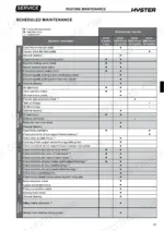
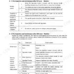
The tank oil change is scheduled to be performed every 3000 hours or 36 months. p. 65
What do I get after purchasing this Hyster S2.4HBE manual?
All 68 pages arrive as one searchable PDF at checkout. Read it at the desk, then take the phone out to the machine.
Am I able to print pages from this Hyster S2.4HBE manual?
Yes. Many mechanics print the section they need for their own shop and bring it to the bench.


Reviews
There are no reviews yet.