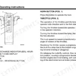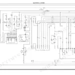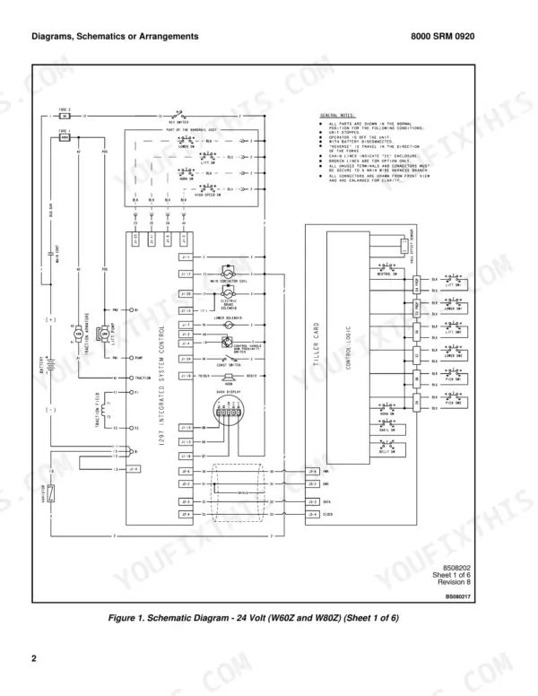
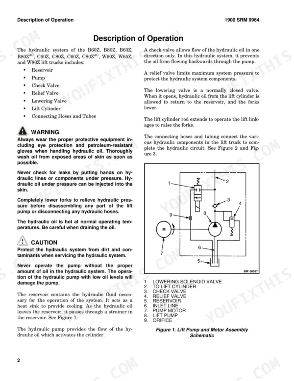
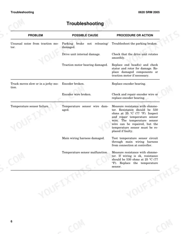
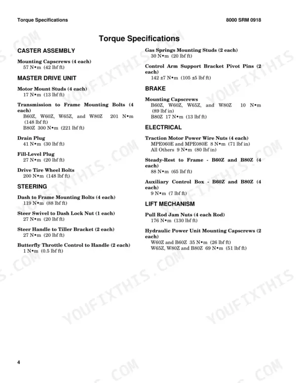
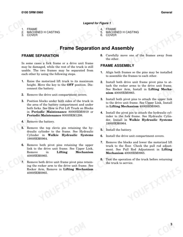
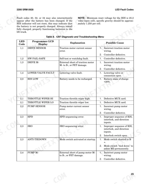
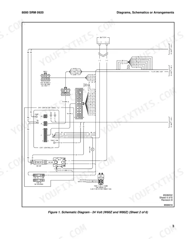
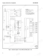
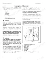
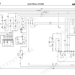
Discharging the capacitors before you pull the AC traction motor is one of the jobs this 366-page Hyster W60Z service manual PDF lays out, and the same book serves the W65Z and W80Z pallet trucks. Electrical wiring diagrams sit in the schematic section, while the hydraulic schematics cover the lift circuit: reservoir, lift pump and motor, lowering valve, relief valve and lift cylinder. Curtis 1297 controller work gets its own chapter, with 1307 and 1311 handset programming, LED fault codes and a control card functional test. Set the control handle prox switch gap at 3.0 to 5.0 mm (0.12 to 0.20 in.), and confirm the temperature sensor reads 530 ohms at 25 °C (77 °F). If your task is splitting the frame, frame separation and assembly are covered as well. Bookmarks and a searchable text layer take you straight to brake air gap adjustment, battery maintenance or the lubrication schedule.
What's Inside This Hyster W60Z, W65Z, W80Z Manual
| System | Pages | Key Topics |
|---|---|---|
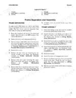
| Frame | 1-7 | Frame Separation, Frame Assembly, Typical Frame Weldments |
| Painting Instructions | 8 | Surface Preparation, Painting, Label Replacement |
| AC Motor Repair | 15-28 | Accessing Drive Unit, Discharging Capacitors, Motor Removal, Motor Installation, Troubleshooting |
| Master Drive Unit | 29-44 | Check Oil Level, Drive Tire Removal, Master Drive Unit Disassembly, Bevel Gear Set, Steering Bearing |
| Steering Mechanism | 45-66 | Control Handle Head, Gas Spring, Steering and Dash Assembly, Troubleshooting |
| Brakes | 67-88 | Brake Check, Brake Coil Check, Brake Assembly Repair, Air Gap Adjustment, Torque Nut Adjustment |
| Walkie Hydraulic Systems | 89-126 | Hydraulic Reservoir, Lift Pump and Motor, Lowering Valve, Relief Valve, Lift Cylinder |
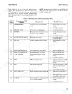
| Curtis 1297 Transistor Motor Controller | 127-176 | Programming Controller, 1307 Programmer Handset, 1311 Programmer Handset, LED Fault Codes, Control Card Functional Test |
| Electrical System | 177-218 | Electrical System Checks, Controller Replacement, Contactor Replacement, Motor Maintenance, Brush Replacement |
| Battery Indicators | 219-254 | Indicators with Meter Movements, Battery Indicators with LCD/LED, Curtis 933-1 Meter, Sevcon Powergauge, SEM Display Panel |
| Lifting Mechanism | 255-282 | Load Wheel, Caster Wheels, Rear Link and Load Wheel Assembly, Pull Rod, Rocker Arm, Upper Link |
| Metric and Inch (SAE) Fasteners | 283-304 | Threaded Fasteners, Strength Identification, Cotter Pins, Fastener Torque Tables |
| Capacities and Specifications | 305-318 | Hydraulic System, Truck Weights, Tires, Torque Specifications, Battery Specifications |
| Periodic Maintenance | 319-346 | Maintenance Schedule, Lubrication Instructions, Battery Maintenance, How to Change Battery |
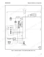
| Diagrams | 347-366 | General Notes, Schematic Diagrams |
Quick Reference Specifications
| Specification | Value | Page |
|---|---|---|
| Traction motor mounting capscrews torque | 17 N·m (13 lbf ft) | p. 23 |
| Temperature sensor resistance | 530 ohms at 25 °C (77 °F) | p. 24 |
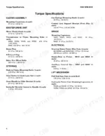
| Control handle prox switch gap | 3.0 to 5.0 mm (0.12 to 0.20 in.) | p. 309 |
| Brake coil resistance | 14.0 ohms | p. 76 |
| Brake capscrew torque | 12 to 14 N·m | p. 77 |
| Relief valve setting (B60Z, B60ZAC, C60Z, C60ZAC, W60Z) | 18.96 MPa (2750 psi) | p. 117 |
| M1 Brake Current Limit | 50 to 350 Amps | p. 134 |
| M1 Acceleration Rate | 0.1 to 3.0 Sec | p. 134 |
| Caster shim gap | not more than 1.50 mm (0.06 in.) | p. 261 |
| Caster shim compression | not more than 1.50 mm (0.06 in.) | p. 261 |
| Drive Tire Wheel Bolt Torque | 200 N•m (148 lbf ft) | p. 311 |
| Drive Tire Wheel Lug Nut Torque | 195 N•m (144 lbf ft) | p. 311 |