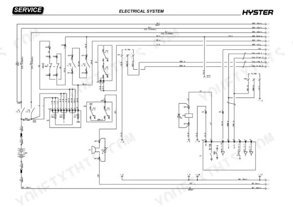
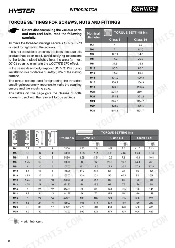
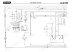
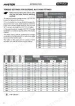
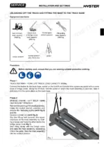
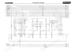
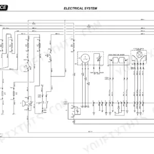
How the Hyster R1.0E, R1.2E and R1.4E retractable trucks are wired, plumbed, set up and maintained is laid out in one 380-page document, OEM ID 4217108. Electrical chapters of this Hyster R1.0E service manual PDF pair wiring diagrams with traction control, steering control, display controls, fuse replacement and contactor replacement. Hydraulic diagrams trace the circuit through the solenoid valves and pressure relief valve, and the mechanical chapters take the mast apart down to its chains and bearings. Rig with a bridge crane rated for 2000 kg where installation calls for one. Torque M30 Class 10 bolts to 594.7 Nm. If your truck has logged an overvoltage or undervoltage alarm, the diagnostics chapter gives the 65V and 11V limits and works through the tester menu and alarm log. Bookmarks and a searchable text layer let you confirm which contactor, fuse or lift pump you are replacing before ordering, though the book carries no parts lists.
What's Inside This Hyster R1.0E, R1.2E, R1.4E Manual
| System | Pages | Key Topics |
|---|---|---|
| Presentation | 13-22 | Truck Presentation, Views of the Truck |
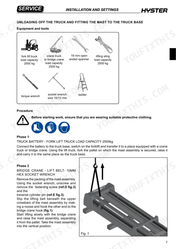
| Installation and Settings | 23-42 | Battery Installation, Fork Assembly, Load Rack Assembly, Contrast Roller Assembly, Level Pre-Selector Programming |
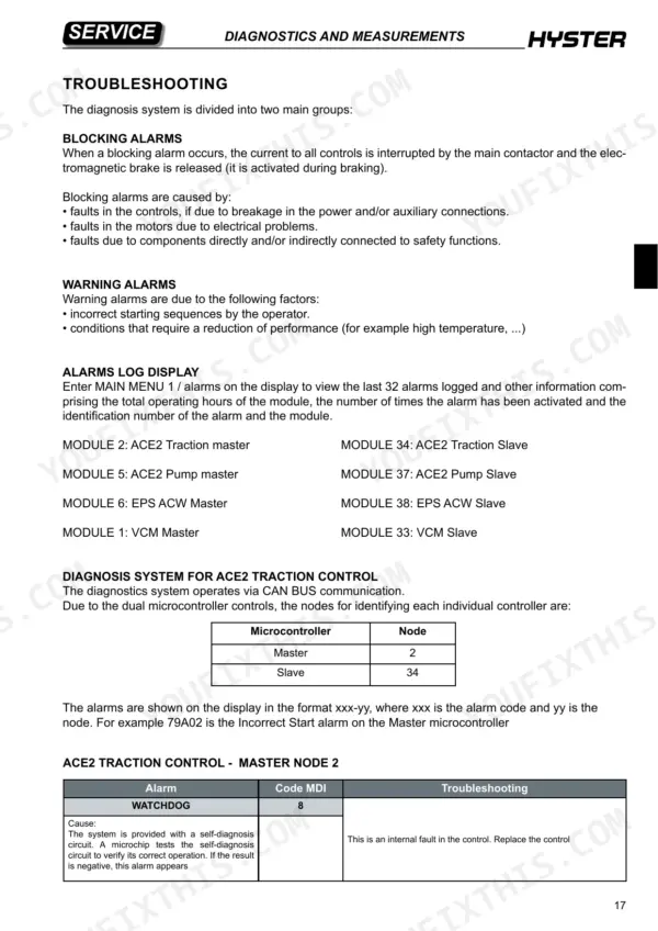
| Diagnostics and Measurements | 43-101 | Module Connectors, Tester Menu, Troubleshooting, Alarm Log, Electrical Component Measurements |
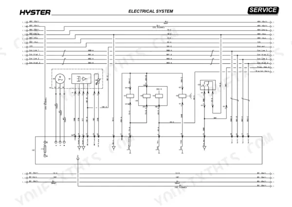
| Electrical System | 102-226 | Wiring Diagrams, Display Controls, Traction Control, Steering Control, Fuse Replacement, Contactor Replacement |
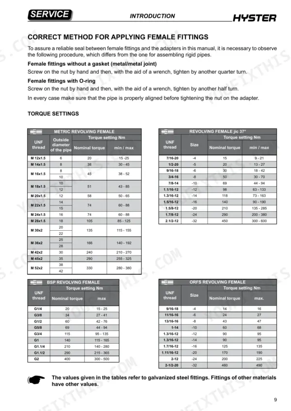
| Hydraulic System | 227-296 | Hydraulic Diagrams, Solenoid Valve Operation, Pressure Relief Valve, Cylinder Disassembly, Lift Pump Replacement, Hydraulic Pipes |
| Mechanics of the Truck Base | 297-324 | Traction Wheel, Load Wheel, Battery Block, Traction Motor, Steering Motor, Retractable Carriage |
| Mast Assembly Mechanics | 325-344 | Support Column, Inner Upright, Intermediate Upright, Bearings, Chains, Chain Tensioner |
| Fork Small Mast Mechanics | 345-356 | Fork Carriage, Mobile Frame, Sliding Skids, Side Shift Cylinder, Hydraulic Circuit Bleeding |
| Reduction Unit | 357-364 | Reduction Unit Components, Reduction Unit Removal, Reduction Unit Disassembly, Reduction Unit Oil |
| Braking System | 365-370 | Traction Motor Electromagnetic Brake, Release Braking, Direction Reversal Braking, Emergency Braking, Parking Brake, Service Brake |
| Routine Maintenance | 371-380 | Oils and Lubricants, Cleaning Products, Scheduled Maintenance, Braking System Maintenance, Hydraulic System Maintenance, Reduction Unit Maintenance |
Quick Reference Specifications
| Specification | Value | Page |
|---|---|---|
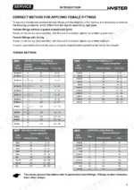
| Torque setting for M3 Class 8 bolt | 4 Nm | p. 8 |
| Torque setting for M3 Class 10 bolt | 5.2 Nm | p. 8 |
| Bridge crane load capacity | 2000 kg | p. 32 |
| Overvoltage limit | 65V | p. 60 |
| Undervoltage limit | 11V | p. 60 |
| Solenoid valve coil resistance | 24.6 Ohm | p. 100 |
| Pump motor power (S3 15%) | 9.9 kW | p. 19 |
| Traction motor power (S2 60 min) | 5.4 kW | p. 19 |
| Battery voltage | 48 V | p. 19 |
| Reduction unit oil capacity | 2.2 litres | p. 363 |
| Reduction unit oil drain cap torque | 22 Nm | p. 363 |
| Reduction unit oil filler cap torque | 22 Nm | p. 363 |
Hyster R1.0E, R1.2E, R1.4E Common Problems This Manual Covers
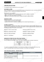
Hyster R1.0E R1.2E R1.4E traction control BATTERY LOW alarm 66 still showing on the display after charging
Charge the battery first. If alarm 66 is still there, measure battery voltage with a voltmeter and compare it to the VOLTAGE BATTERY parameter, as the chart on page 61 lays out. If the readings differ, correct it with the ADJUST BATTERY function. Never check charge by laying metal items across the terminals (page 5). If the alarm persists, replace the control.
Manual Section: ACE2 Traction Control Diagnostics p. 61Main contactor coil energized but contacts never close, CONTACTOR OPEN alarm 38 on traction control
Disconnect the battery and discharge the capacitors before opening the electric compartment, per pages 5 and 372. Inspect the main contactor contacts following page 61 and replace the contactor if they are bad. Do not file or lubricate the contacts (page 372); that can make them stick. If the contacts work correctly, the fault is inside the control, so replace it.
Manual Section: ACE2 Traction Control Diagnostics p. 61Traction control LOGIC FAILURE #1 alarm 19 appearing during acceleration or when the brake releases
Check battery charge state and power connections if the alarm hits during acceleration; that points to undervoltage. If it appears as the brake releases, suspect overvoltage and check the contactor contacts and power connections. Disconnect the battery before working on those connections (page 5). The control trips above 65 V or below 11 V, per page 60. If supply voltage holds steady and the alarm shows at every key ON, replace the control.
Manual Section: ACE2 Traction Control Diagnostics p. 60Traction control VDC LINK OVERV. alarm 202 showing every time the truck is powered on
Disconnect the battery before working on the electrical system (page 5). Check the power cable connections at the battery, the contactor and the control +Batt and -Batt terminals, then torque them to 13 Nm to 15 Nm as page 63 specifies. The alarm threshold is 65 V. If the supply line checks out and the alarm returns at every power on, replace the logic board.
Manual Section: ACE2 Traction Control Diagnostics p. 63Traction control encoder malfunction with ENCODER ERROR alarm 82 showing on the display
Disconnect the battery before working on the electrical system (page 5). Check the encoder electrically and mechanically, along with its wiring, following page 62. Verify the encoder is installed correctly; if it rotates in its housing, it will set this alarm. Electromagnetic disturbance can also trigger it, and in that case replace the encoder. If the alarm returns with a new encoder, replace the control.
Manual Section: ACE2 Traction Control Diagnostics p. 62INCORRECT START alarm 79 at startup with traction request or man present sensor active
Verify no traction request is active and the man present sensor is not pressed when the key goes on, since a wrong operator sequence sets this alarm. Then check the wiring and the microswitches following page 62, with the battery disconnected before any electrical work (page 5). If wiring and microswitches check out, the logic board is the likely fault; replace the control.
Manual Section: ACE2 Traction Control Diagnostics p. 62Frequently Asked Questions
How do I calibrate the controller voltage on a Hyster R1.0E/R1.2E/R1.4E?
To set the battery voltage on the VCM module, connect a programmer and select 'VCM module / config menu adjustment / adjust battery'. Measure the exact battery voltage between the negative power connection (-Batt) on an inverter and pin 28 of connector A on the VCM module. Set the 'adjust battery' parameter to this measured value, then turn the machine off and back on. p. 38
What are the replacement specifications for the 48V traction battery on the Hyster R1.0E, R1.2E, R1.4E?
The battery must be in compliance with DIN 43531/35/36 (A, B, or C). For model R1.0E/R1.2E, weights range from 514 kg to 992 kg depending on the capacity (48/280 to 48/620 V/Ah). For model R1.4E, weights range from 712 kg to 997 kg (48/420 to 48/620 V/Ah). p. 25
What is the torque spec for tightening the reduction unit to the plate on the Hyster R1.0E, R1.2E, R1.4E?
When installing the reduction unit, the screws securing the reduction unit to the plate must be tightened using a torque wrench to a torque of 88 Nm. p. 106
What is the oil capacity and type for the GK20 reduction unit on the Hyster R1.0E, R1.2E, R1.4E?
The GK20 reduction unit requires approximately 2.2 liters of FUCHS TITAN CYTRAC HSY SAE 75W-90 oil. The oil filler cap must be tightened to 22 Nm. p. 109
How do you perform the air bleeding procedure for the lift cylinder?
After maintenance, raise the forks with no load by approximately 300mm, stop for 10 seconds, and repeat until all air is removed from the bleed valve. Finally, take the forks to full height and tighten the bleed screw (ref.B fig.1) to seal the system. p. 18
Is this Hyster R1.0E Service Manual a digital download?
One searchable PDF covering 380 pages, delivered instantly. No disc, no shipping, no waiting on the post.
Am I free to print this Hyster R1.0E Service Manual?
Yes. Many mechanics print the section they need for their own shop and bring it to the bench.