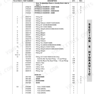
One book stands between a 600 series boom lift and the rental yard's dead row: JLG publication 3120840, a JLG 600S service and maintenance manual PDF whose 272 pages cover five telescopic and articulating variants of this aerial work platform. Hydraulic schematics trace each circuit from the M46 variable displacement pump through the control valves, wiring diagrams map the electrical side, and a dedicated section teaches the hand held analyzer: connection, access levels, and machine personality settings. Cylinder work runs from theory of operation through repair, removal, and drift testing. Shim your main boom wear pads to within 0.8 mm, replace tower boom pads once wear passes 1.6 mm, and pull A model wheel lugs to 170 ft. lbs. (231 Nm). Troubleshooting a fault code from the basket is miserable. Buy this bookmarked, text-searchable PDF once and it is yours for as long as you run the machine.
What's Inside This JLG 600S-660SJ Series Manual
| System | Pages | Key Topics |
|---|
| Introduction - Maintenance Safety Precautions | 5-18 | Hydraulic System Safety, Maintenance |
| Specifications | 19-34 | Capacities, Component Data, Performance Data, Function Speeds, Torque Requirements, Lubrication, Pressure Settings, Cylinder Specifications |
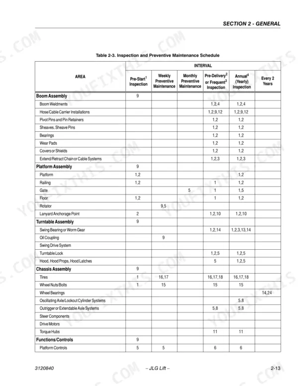
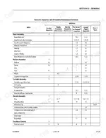
| General | 35-50 | Machine Preparation, Inspection, And Maintenance, Service and Guidelines, Lubrication and Information |
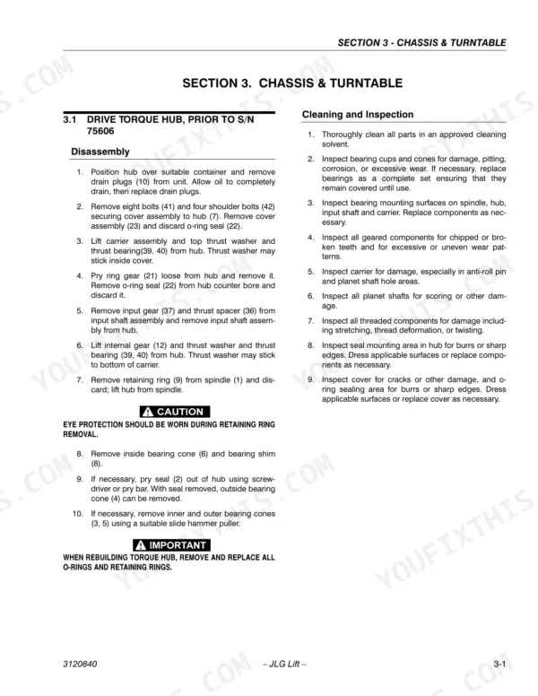
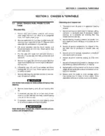
| Chassis & Turntable | 51-102 | Drive Torque Hub, Prior to S/N 75606, Torque Hub, Drive, S/N 75606 to Present, Drive Brake - Mico, Free Wheeling Option |
| Boom & Platform | 103-132 | Boom Rope Torquing Procedures, Wear Pads, Wire Rope, Boom Maintenance, Tower Boom, Articulating Jib Boom, Limit Switches and Cam Valve Adjustment, Platform |
| Hydraulics | 133-182 | Cylinders - Theory of Operation, Cylinder Checking Procedure, Cylinder Repair, Cylinder Removal and Installation, Variable Displacement Pump, Valves - Theory of Operation |
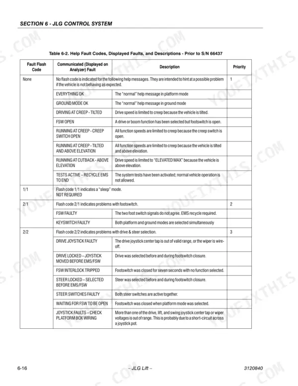
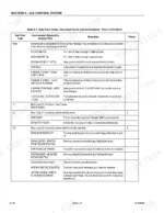
| Jlg Control System | 183-226 | Introduction, To Connect the Jlg Control System Analyzer, Using the Analyzer, Changing the Access Level of the Hand Held Analyzer, Parameters Using the Hand Held Analyzer |
| Schematics | 227-272 | Troubleshooting, Hydraulic Circuit Checks |
Quick Reference Specifications
| Specification | Value | Page |
|---|
| All Models |
| Wheel Lugs (A Models) | 170 ft. lbs. (231 Nm) | p. 22 |
| Contact wire pull force | 1 or 2 lbs. | p. 43 |
| Screwdriver blade width for wedge lock disassembly | 4.8 mm (3/16") | p. 43 |
| Replace wear pads (Tower Boom A Models) when worn within | 1.6 mm | p. 103 |
| Shim up wear pads (Main Boom) to within | 0.8 mm | p. 103 |
| Torque retract adjusting nuts (S Models) | 20 Nm | p. 103 |
| Foot switch travel adjustment | 6.35 mm | p. 132 |
| Actuator end cap torque | 54 - 68 Nm | p. 130 |
| Maximum pressure for pressure-washing electrical/electronic components | 750 PSI (52 BAR) | p. 183 |
| Minimum distance for pressure-washing electrical/electronic components | 12 inches (30.5 cm) | p. 183 |
| 600S, 600SJ, 660SJ |
| Fuel Tank Capacity | 148 Liters | p. 19 |
| 600A, 600AJ |
| Fuel Tank Capacity | 114 Liters | p. 19 |