Part of the John Deere Repair Manuals.
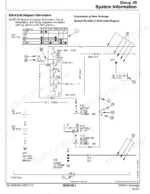
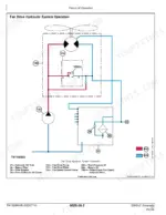
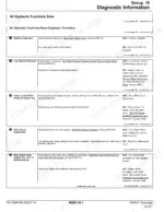
Every one of the 970 pages in this John Deere 250GLC Excavator Technical Manual (OEM #TM13208X19, 2013-2016) is built around one job: getting your 250GLC back to spec without the guesswork. Open it to full wiring diagrams covering every harness on the machine, from the pump harness to the DEF harness, plus complete hydraulic schematics for the pilot system, control valve, and swing circuit. You get diagnostic trouble code tables cross-referenced to component checks, so a fault code actually points you somewhere useful. Set hydraulic oil temperature sensor readings against DTC 9001-10-100 and 9001-10-101, or check the air cleaner restriction alarm at 9001-40-9, straight from the factory data. Your multimeter and a hunch only get you so far on a machine this complex. This bookmarked PDF opens on your laptop or phone, jumps straight to the right section, and gets you back to digging.
What's Inside This John Deere 250GLC, 250G Manual
| System | Pages | Key Topics |
|---|---|---|
| General Information | 9-30 | Safety Information, Protective Equipment, Machine Modifications, High-Pressure Fluids, Prevent Fires, Exhaust Filter Ash Handling and Disposal |
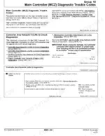
| Diagnostics | 31-178 | Main Controller (Mcz) Diagnostic Trouble Codes, Engine Control Unit (ECU) Diagnostic Trouble Codes, Monitor Controller (Dsz) Diagnostic Trouble Codes |
| Operational Checkout Procedure | 179-230 | Operational Checkout, Diagnostic Trouble Code Check, Key Switch Off Checks, Key Switch on Engine Off Checks, Key Switch on Engine on Checks |
| Engine | 231-255 | Engine Identification, Fuel System Component Location, Cooling System Component Location, Diesel Exhaust Fluid (DEF) System Component Location, Cold Weather Starting Aid |
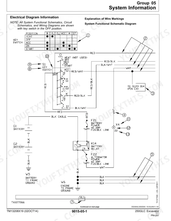
| Electrical System | 256-562 | System Functional Schematic, Cab Harness (W1) Wiring Diagram, Controller Area Network (CAN) Theory of Operation, Starting and Charging Circuit Theory of Operation |
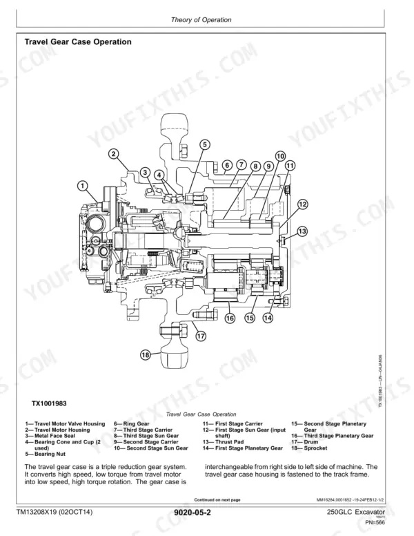
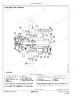
| Power Train | 563-576 | Track Adjuster and Recoil Spring Operation, Travel Gear Case Operation, Noisy or Loose Track Chain, Excessive Oil Leakage From Front Idler, Track Rollers, Or Carrier Rollers |
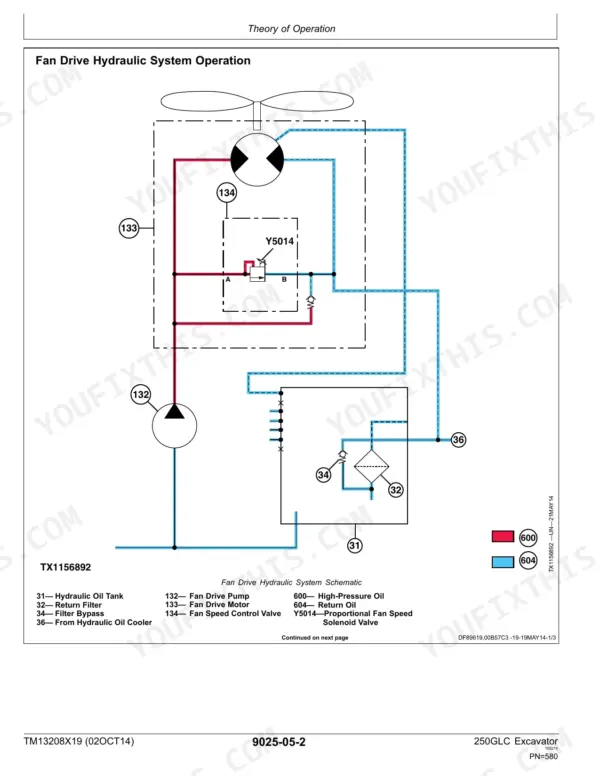
| Hydraulic System | 577-926 | Hydraulic System Operation, Fan Drive Hydraulic System Operation, Pilot System Operation, Control Valve Operation, Main Relief Valve Circuit Operation |
| Heating and Air Conditioning | 927-952 | Air Conditioning System Cycle of Operation, Air Conditioning System Does Not Operate, Heating System Does Not Warm Interior of Cab, R134a Refrigerant Cautions and Proper Handling |
| Dealer Fabricated Tools | 8 | DFT1218 Split Flange Hose Cap and Other Dealer-Fabricated Service Tools |
Quick Reference Specifications
| Specification | Value | Page |
|---|---|---|
| torque values | present | p. 2 |
| diagnosis | present | p. 2 |
| specifications | present | p. 2 |
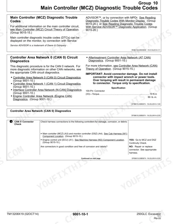
| Hydraulic Oil Temperature Sensor Circuit High Input | 9001-10-100 | p. 29 |
| Air Cleaner Restriction Alarm | 9001-40-9 | p. 30 |
| Battery Disconnect Indicator Light Short to Ground | 9001-20-11 | p. 28 |
| Alternator Excitation Fault | 9001-20-8 | p. 29 |
| Alternator Alarm | 9001-40-1 | p. 30 |
| Hydraulic Oil Filter Restriction Alarm | 9001-40-8 | p. 30 |
| Battery | 45 A Fuse | p. 267 |
| Fuel Transfer Pump 10 A Fuse | 10 A | p. 293 |
| Electronic Injector (Cylinder 1) | Y1 | p. 475 |
John Deere 250GLC, 250G Common Problems This Manual Covers
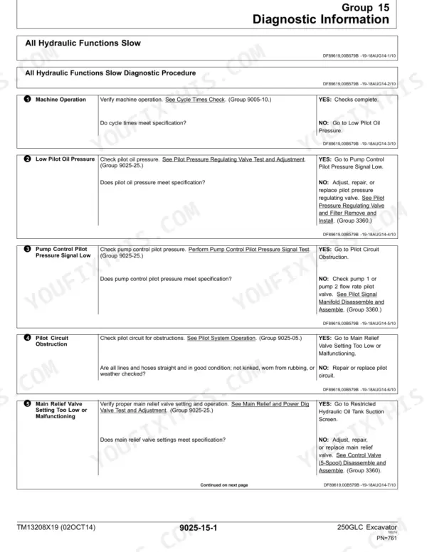
John Deere 250GLC excavator arm drifting with pilot control neutral or all hydraulic functions moving slowly
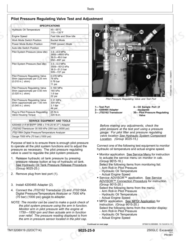
Warm up the hydraulic oil to the target temperature of 45 to 55°C as noted on page 879. Inspect the main relief valve setting. Test the travel motor with the track raised to ensure leakage remains below the maximum 10.0 L/min (2.6 gpm) limit found on page 917.
Manual Section: All Hydraulic Functions Slow Diagnostic ProcedureEngine cranks very slowly or completely fails to start during severe cold weather operation
Measure battery voltage directly at the terminals to verify it reads between 24 to 28 volts. Refer to page 245 and confirm the glow plug preheat time reaches 15 seconds at -15°C (5°F). Check the 45 A fuse shown on page 267 and replace if blown.
Manual Section: Engine Control Unit (ECU) Diagnostic Trouble CodesBattery voltage drops rapidly during operation and alternator alarm illuminates on the monitor
Test the alternator D+ voltage on the 24 V system to verify it produces 27.5 VDC or greater as shown on page 547. Measure the AC voltage between terminal W and ground to confirm it reads 12 to 14 VAC. Check the 65 A alternator fuse on page 267.
Manual Section: Information Controller (ICZ) Diagnostic Trouble CodesHeating system blows cold air and does not warm the interior of the cab
Inspect the cab fresh air filter and recirculating air filter for severe restriction. Verify the engine coolant temperature reaches 93°C as specified on page 254. Check the heater system 20 A fuse marked HEATER on page 931. Clear any debris blocking the heater core air flow.
Manual Section: Heating System Does Not Warm Interior of Cab Diagnostic ProcedureFrequently Asked Questions
How do I reset the John Deere 250GLC travel alarm?
To reset the travel alarm, press and release the travel alarm cancel switch (S13). The alarm must sound for 10 seconds before deactivating. The travel alarm (H4) will also reset when the control levers are returned to the neutral position. p. 205
Where is the main fuse located on the John Deere 250GLC?
The main battery power fuses, F60 (Alternator 65 A Fuse) and F61 (Battery 45 A Fuse), are located in the engine compartment. These are part of Fuse Block 2, which also contains other fuses for various systems. p. 267
How do I clear engine fault codes on the John Deere 250GLC?
To clear engine fault codes, turn the key switch to the ON position. After turning the key switch on, clear all codes and then check for any remaining Diagnostic Trouble Codes (DTCs). This process is typically done via the monitor or diagnostic tools. p. 40
What is the specified operating temperature range for the hydraulic oil?
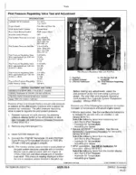
The specified operating temperature range for the hydraulic oil is 45—55°C (110—130°F). This temperature range is crucial for various tests and adjustments, including the Pilot Pressure Regulating Valve Test and Adjustment. p. 881
What format is this John Deere 250GLC manual in?
You get a 970-page searchable PDF that downloads instantly after checkout. Open it on your laptop, tablet, or phone, and bring it right to the shop floor.
Is this John Deere 250GLC Technical Manual printable?
Yes. Print individual pages or full chapters for your own shop use, on letter or A4 paper.
Are hydraulic diagrams part of this John Deere 250GLC Technical Manual?
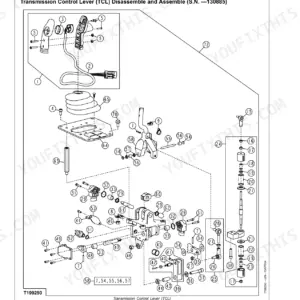
Yes. The manual includes a hydraulic system diagram covering the main circuits.