
Part of the John Deere Repair Manuals.
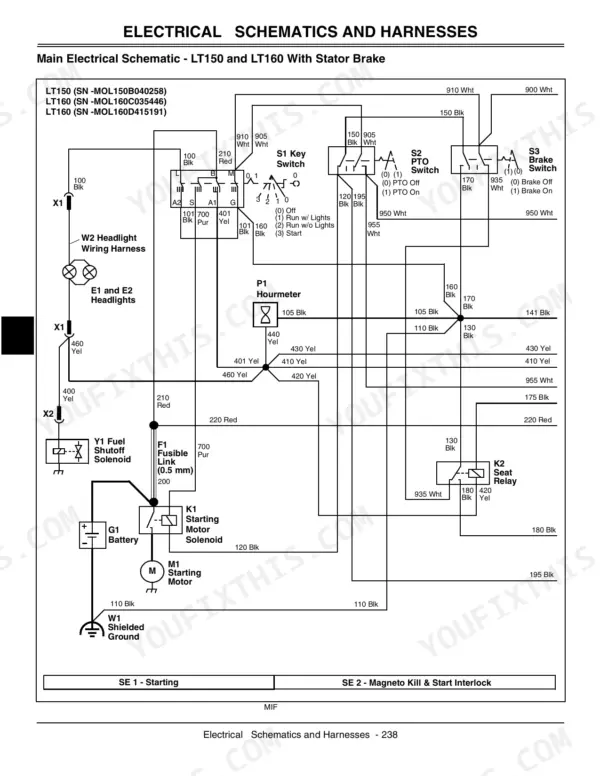
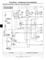
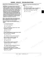
Electrical work fills the largest stretch of TM1975, the 532-page John Deere LT150 technical manual pdf that also covers the LT160, LT170, LT180 and LT190 lawn tractors, mapping the cranking circuit, the charging and shunt circuit, and the PTO with RIO circuit before you ever pull a harness loose. Wiring schematics trace each conductor through the ignition and shutoff circuit, and separate engine chapters break out Kohler, Briggs & Stratton and both Kawasaki FH500V and FH580V builds with their own troubleshooting trees, governor and choke adjustments, and cylinder head teardowns. Deck lift, blade removal, transaxle and traction drive belt service follow. Set the belt tensioner compression spring caps at 32 to 34 mm (1.26 to 1.34 in.), gap a Kohler plug at 1.0 mm (0.040 in.), and torque it to 27.1 N.m (240 lb-in.). Chasing a dead PTO circuit with a test light and no diagram wastes a Saturday. Bookmarks and a live text layer drop you into the right chapter in seconds.
What's Inside This John Deere LT150–LT190 Series Manual
| System | Pages | Key Topics |
|---|---|---|
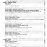
| Introduction | 3-4 | Manual Description, Table of Contents, Identification Numbers, Tools and Materials, Component Location |
| Safety | 5-8 | |
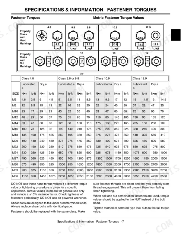
| Specifications and Information | 9-16 | Fastener Torques, Gasoline, Engine Oil, Transmission Oil, Gear Case Oil, Gear Transmission Grease, Lubricants, Oil Filters |
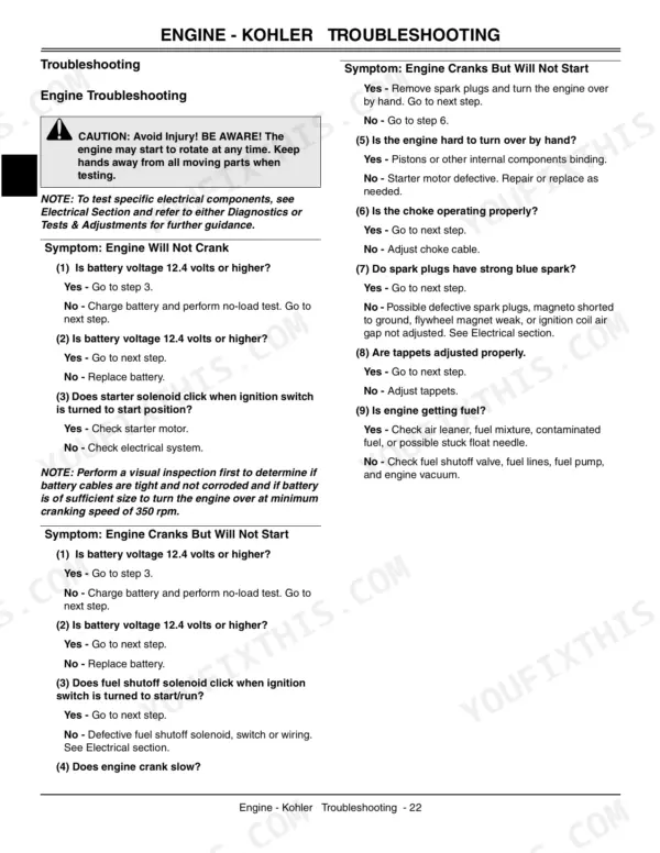
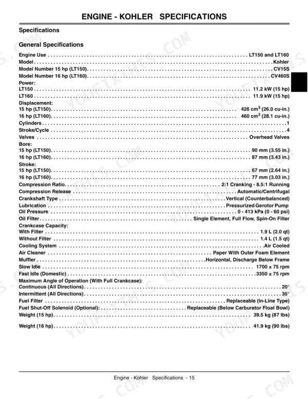
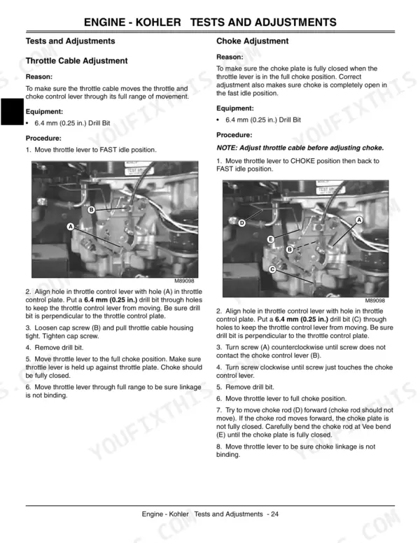
| Engine - Kohler | 17-66 | Engine Specifications, Engine Troubleshooting, Throttle Cable Adjustment, Choke Adjustment, Governor Adjustment, Fuel Pump Removal, Engine Removal, Cylinder Head Removal |
| Engine - Briggs & Stratton | 67-122 | Engine Specifications, Engine Diagnostics, Throttle Cable Adjustment, Choke Cable Adjustment, Fuel Shutoff Solenoid, Governor Adjustment, Cylinder Head Removal, Valve Removal |
| Engine - Kawasaki (FH500V) | 123-172 | Engine Specifications, Lubrication System, Engine Troubleshooting, Throttle Cable Adjustment, Choke Cable Adjustment, Governor Adjustment, Fuel Pump Removal, Cylinder Head Removal |
| Engine - Kawasaki (FH580V) | 173-228 | Engine Specifications, Lubrication System, Engine Troubleshooting, Throttle Cable Adjustment, Choke Cable Adjustment, Governor Adjustment, Fuel Pump Removal, Cylinder Head Removal |
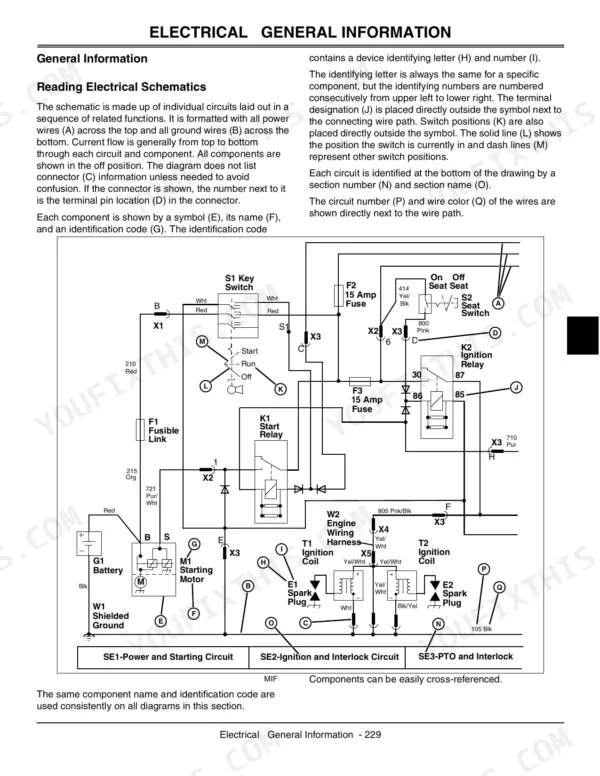
| Electrical | 229-382 | Electrical Schematics, Wiring Harnesses, Power Circuit Operation, Cranking Circuit Operation, Ignition and Shutoff Circuit, Charging and Shunt Circuit, PTO with RIO Circuit |
| Power Train - Gear | 383-404 | Drive Components, PTO Components, Shift Linkage, Transaxle Components, Clutch Pedal, Brake System |
| Power Train - Hydrostatic | 405-430 | Transaxle Components, Drive Components, Forward and Reverse Pedals, Traction Drive Belt System, Freewheel System |
| Steering | 431-440 | Steering System Components, Toe-In Adjustment, Steering Gear Assembly, Front Axle |
| Brakes | 441-456 | Brake Pedal and Linkage, Brake System, Park Brake, Brake Linkage Adjustment, Brake Assembly |
| Attachments | 457-514 | Deck Lift Assembly, Mower Deck, Blade Removal, Mower Deck Removal, Mower Deck Lift Linkage, Idlers |
| Miscellaneous | 515-522 | Front Wheel, Front Wheel Bearing, Rear Wheel, Hood, Seat and Seat Support, Fuel Tank |
Quick Reference Specifications
| Specification | Value | Page |
|---|---|---|
| All Models | ||
| Spark Plug Gap | 1.0 mm (0.040 in.) | p. 20 |
| Spark Plug Gap - LT150/LT160/LT190 | 0.75 mm (0.030 in.) | p. 175 |
| Distance Between Plastic Caps of Compression Spring (Belt Tensioner Assembly) | 32 - 34 mm (1.26 - 1.34 in.) | p. 420 |
| Compression Spring | 32 - 34 mm (1.26 - 1.34 in.) | p. 420 |
| Idler Nut | 26 N•m (228 lb-in.) | p. 407 |
| Traction drive belt guide clearance | 3 mm (0.125 in.) | p. 470 |
| LT150, LT160 | ||
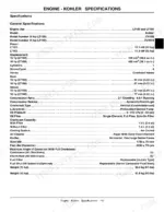
| Spark Plug Gap (Kohler) | 1.0 mm (0.040 in.) | p. 20 |
| LT170 | ||
| Spark Plug Gap (Briggs & Stratton) | 0.76 mm (0.030 in.) | p. 69 |
| LT180 | ||
| Spark Plug Gap (Kawasaki FH500V) | 1.0 mm (0.040 in.) | p. 125 |
| LT190 | ||
| Spark Plug Gap (Kawasaki FH580V) | 0.75 mm (0.030 in.) | p. 175 |
| 38 inch, 42C, 48C | ||
| Brake Pad To Spindle clearance | 2 - 3 mm (0.79 - 0.12 in.) | p. 475 |
| Minimum Brake Pad Thickness | 2 mm (0.079 in.) | p. 470 |
John Deere LT150–LT190 Series Common Problems This Manual Covers
Engine overheats and smells hot after twenty minutes of mowing
Shut it down and clean the intake screen and cooling fins with compressed air; packed grass chaff is the usual culprit. Verify oil level sits at the full mark, 1.7 L (1.8 qt) with filter on the FH500V per page 125. Avoid extended low idle, and follow the overheating checks in the engine troubleshooting section.
Manual Section: Engine - Kawasaki (FH500V) p. 125No forward drive or the tractor creeps and slips on hills
Inspect the traction drive belt for glazing and cracked cogs, then measure the belt tensioner compression spring between the plastic caps: it must sit at 32 to 34 mm (1.26 to 1.34 in.) per page 420. Set the belt guide clearance to 3 mm (0.125 in.) and torque the flat idler nut to 26 N•m (228 lb-in.).
Manual Section: Power Train - Hydrostatic p. 420Mower deck vibrates badly and belt squeals or throws off the spindles
Remove the deck and spin each spindle by hand, listening for bearing rumble and checking for shaft wobble. Measure the brake pad to spindle clearance at 2 to 3 mm per page 475, and replace any pad thinner than 2 mm (0.079 in.). Inspect the idler pulleys and re-route the belt exactly as the deck diagrams show.
Manual Section: Attachments p. 475Frequently Asked Questions
What are the torque specifications for the LT160 and LT180 engine mounting bolts?
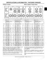
The engine mounting cap screws for the LT160 and LT180 models must be tightened to 32 N•m (24 lb-ft). p. 24
How do you fix john Deere LT150 won't start or has no power when you turn the key?
Check the battery first, then work the cranking circuit diagnostics in the electrical section starting at page 229. Pull the spark plug and set the gap to 1.0 mm (0.040 in.) per page 20, then torque it to 27.1 N•m (240 lb-in.). Confirm the seat and brake safety switches close before condemning the ignition switch. p. 229
How do you fix engine starts fine but quits the moment the brake pedal is released?
Verify the seat switch and park brake switch continuity against the wiring diagram before replacing parts. Adjust the brake linkage in the brakes section beginning on page 441 so the switch plunger fully seats. Inspect the harness connector under the fender deck for corroded pins and green wire rot. p. 441
How do you fix engine bogs down and loses power under mowing load in tall grass?
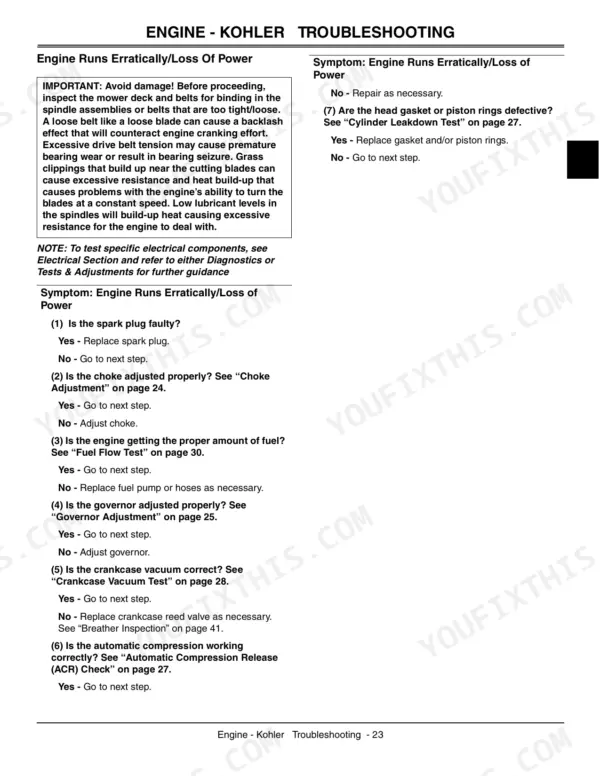
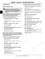
Clean or replace the air cleaner element and drain any fuel older than 30 days. Check the oil level: the Kohler crankcase holds 1.9 L (2.0 qt) with a filter, listed on page 19. Then walk the loss of power chart on pages 26 and 27 and adjust the governor linkage if engine speed sags off. p. 26
What format is this John Deere LT150–LT190 Series manual in?
All 532 pages arrive as one searchable PDF at checkout. Read it at the desk, then take the phone out to the machine.
Can I print just the pages I need from this John Deere manual?
Yes. Many buyers print one chapter at a time for their own shop and keep the rest on a tablet.
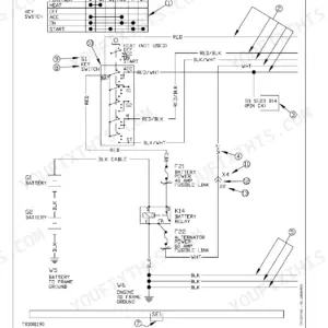
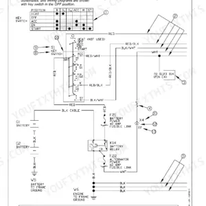
Does this John Deere LT150–LT190 Series manual show the machine's wiring?
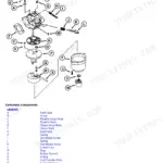
Yes, a wiring diagram for the John Deere LT150–LT190 Series electrical system is in this Technical Manual. Page 233 carries one of them.








Reviews
There are no reviews yet.