
![John Deere 9540i 9560i 9580i 9640i 9660i 9680i and 9780i CTS Repair Manual [Combines]](https://youfixthis.com/wp-content/uploads/2012/02/Manual_Download-300x300.jpg)
Part of the John Deere Repair Manuals.
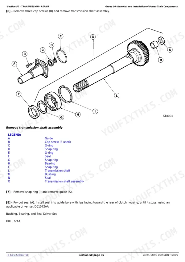
This is the factory John Deere technical manual TM-series coverage for the 5310N, 5410N, and 5510N narrow orchard and vineyard tractors built 1997-2001. It is the combined book: the repair half walks cylinder head, injection pump, clutch, MFWD, brakes, and rockshaft work with torque values and special tools, and the operation-and-tests half gives you theory of operation, pressure test procedures, diagnosis charts, and full electrical wiring diagrams with component locations. All three PowerTech diesels are covered separately - the 53 hp and 72 hp 2.9L in the 5310N/5410N and the 80 hp 4.5L in the 5510N - so specs like oil capacity and pump flow are listed per model. About 1,000 pages, searchable PDF.
What's Inside This John Deere 5310N-5510N Manual
| System | Pages | Key Topics |
|---|---|---|
| Safety | 7-25 | Safety Information |
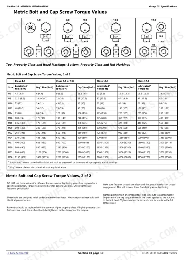
| General Information | 26-58 | Engine and Machine Specifications, Capacities, Torque Values, Fuel and Lubricants, Break-In |
| Engine - Repair | 59-72 | Cylinder Head, Pistons, Crankshaft, Timing, PowerTech Diesel Repair |
| Fuel and Air Intake Systems - Repair | 73-89 | Fuel Injection Pump, Nozzles, Filters, Air Intake |
| Electrical System - Repair | 90-117 | Alternator, Starter, Batteries, Lighting, Wiring Repair |
| Transmission - Repair | 118-257 | Clutch, Transmission, PTO, Differential Repair |
| Drive Systems - Repair | 258-316 | MFWD, Front Axle, Final Drives |
| Steering and Brake Systems - Repair | 317-372 | Power Steering, Steering Cylinder, Brakes |
| Hydraulic System - Repair | 373-457 | Hydraulic Pump, Rockshaft, Selective Control Valves, Hitch |
| Miscellaneous - Repair | 458-516 | Frame, Three-Point Hitch, Miscellaneous |
| Operator'S Station - Repair | 517-585 | |
| Electrical System - Operation and Tests | 586-781 | Electrical Operation, starting/charging/lighting System Tests, Wiring Diagrams, Component Locations |
| Power Train - Operation and Tests | 782-845 | Transmission and Clutch Operation, Pressure Tests, Diagnosis |
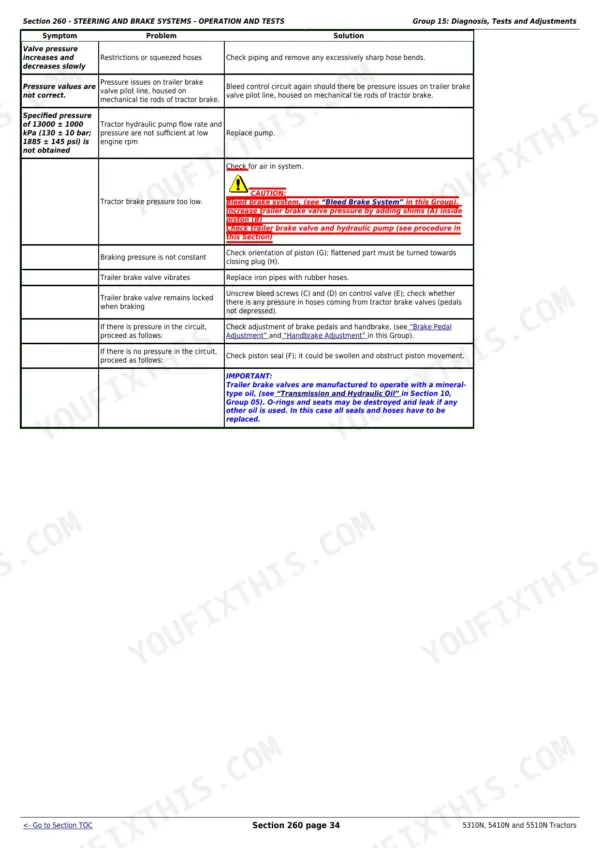
| Steering and Brake Systems - Operation and Tests | 846-895 | Steering and Brake Operation, Pressure Tests |
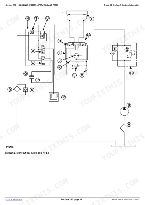
| Hydraulic System - Operation and Tests | 896-976 | Hydraulic Operation, Pump and SCV Pressure Tests, Rockshaft Tests |
| Air-Conditioning System- Operation and Tests | 977-1001 | Air Conditioning Operation and Tests |
| Special Tools - Dealer-Manufactured | 1002-1007 | Dealer-Manufactured Special Tool Drawings |
Quick Reference Specifications
| Specification | Value | Page |
|---|---|---|
| 5310N | ||
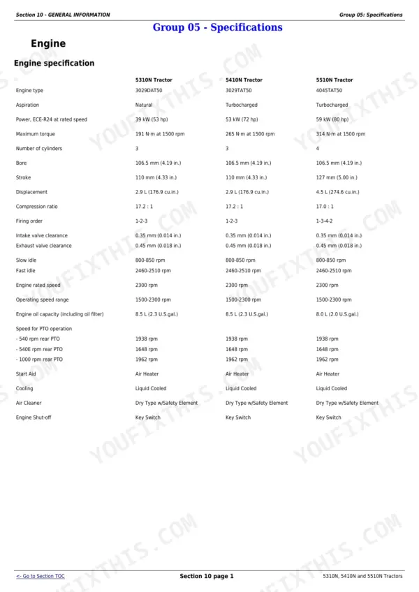
| Power, ECE-R24 at rated speed, 5310N | 39 kW (53 hp) | p. 26 |
| Maximum torque, 5310N | 191 N·m at 1500 rpm | p. 26 |
| 5410N | ||
| Power, ECE-R24 at rated speed, 5410N | 53 kW (72 hp) | p. 26 |
| Maximum torque, 5410N | 265 N-m at 1500 rpm | p. 26 |
| 5510N | ||
| Power, ECE-R24 at rated speed, 5510N | 59 kW (80 hp) | p. 26 |
| Maximum torque, 5510N | 314 N·m at 1500 rpm | p. 26 |
| Stroke, 5510N | 127 mm (5.00 in.) | p. 26 |
| Displacement, 5510N | 4.5 L (274.6 cu.in.) | p. 26 |
| Engine oil capacity (including oil filter), 5510N | 8.0 L (2.0 U.S.gal.) | p. 26 |
| Hydraulic System Pump displacement - Implement, 5510N | 22.7 cm³ (1.39 cu.in.) | p. 27 |
| Hydraulic System Pump displacement - Optional | 28.79 cm³ (1.76 cu.in.) | p. 27 |
| Hydraulic System Flow rate - Implement, 5510N | 47 L/min (12.4 gpm) | p. 27 |
| Hydraulic System Flow rate - Optional | 59.6 L/min (15.8 gpm) | p. 27 |
| SCV flow rate at Engine rated speed 2300 rpm, 5510N | 46.5 L/min (12.2 gpm) | p. 27 |
| SCV flow rate - Optional | 59.6 L/min (15.8 gpm) | p. 27 |
| All Models | ||
| Bore | 106.5 mm (4.19 in.) | p. 26 |
| Intake valve clearance | 0.35 mm (0.014 in.) | p. 26 |
| Exhaust valve clearance | 0.45 mm (0.018 in.) | p. 26 |
| Slow idle | 800-850 rpm | p. 26 |
| Fast idle | 2460-2510 rpm | p. 26 |
| Engine rated speed | 2300 rpm | p. 26 |
| Operating speed range | 1500-2300 rpm | p. 26 |
| Speed for PTO operation - 540 rpm rear PTO | 1938 rpm | p. 26 |
| Speed for PTO operation - 540E rpm rear PTO | 1648 rpm | p. 26 |
| Speed for PTO operation - 1000 rpm rear PTO | 1962 rpm | p. 26 |
| Hydraulic System Pump displacement - Steering | 11.9 cm³ (0.73 cu.in.) | p. 27 |
| Hydraulic System Flow rate - Steering | 24.5 L/min (6.5 gpm) | p. 27 |
| Hydraulic System Maximum pressure - Steering | 13000-13500 kPa (130-135 bar; 1885-1958 psi) | p. 27 |
| Hydraulic System Maximum pressure - Implement | 18000-18500 kPa (180-185 bar; 2610-2683 psi) | p. 27 |
| Outer diameter of disks | 165 mm (6.5 in.) | p. 27 |
| Inner diameter of disks | 110 mm (4.3 in.) | p. 27 |
| Electrical System Type | 12-volt, negative ground | p. 29 |
| Battery | 12 volt, 100 Ah | p. 29 |
| 5310N, 5410N | ||
| Stroke (5310N, 5410N) | 110 mm (4.33 in.) | p. 26 |
| Displacement (5310N, 5410N) | 2.9 L (176.9 cu.in.) | p. 26 |
| Engine oil capacity (including oil filter) (5310N, 5410N) | 8.5 L (2.3 U.S.gal.) | p. 26 |
| Hydraulic System Pump displacement - Implement (5310N, 5410N) | 20 cm³ (1.22 cu.in.) | p. 27 |
| Hydraulic System Flow rate - Implement (5310N, 5410N) | 41.4 L/min (10.9 gpm) | p. 27 |
| SCV flow rate at Engine rated speed 2300 rpm (5310N, 5410N) | 41.4 L/min (10.9 gpm) | p. 27 |
John Deere 5310N-5510N Common Problems This Manual Covers
Engine knocks under load
The diagnosis points to insufficient oil or an injection pump out of time. Check oil level and pressure first, then verify pump timing using the procedure in Section 30 - Fuel and Air Intake Systems. If bearings are suspect, Section 20 covers crankshaft and piston inspection with wear limits.
Manual Section: Section 30 - Fuel and Air Intake Systems - RepairStarter inoperative or cranking slowly
Rule out the interlocks first: shift lever in gear or PTO engaged kills the start circuit. Then load-test the battery and check fuses. Section 240 walks the starting circuit tests with wiring diagrams; starter removal and repair itself is in Section 40 - Electrical System.
Manual Section: Section 240 - Electrical System - Operation and TestsAll cab electrical switches dead at once
When everything in the cab dies together, the diagnosis chart points at a loose, defective, or blown fusible link rather than individual fuses. Section 240's component location drawings show where the links sit, and Section 40 covers wiring repair once you have found the failed link.
Manual Section: Section 240 - Electrical System - Operation and TestsWeak hydraulics or hitch will not lift
Before pulling the pump, run the pressure tests in Section 270: implement circuit should hold 18000-18500 kPa (180-185 bar). The section covers pump flow tests, SCV and rockshaft diagnosis, so you know whether it is the pump, relief valve, or rockshaft before ordering parts. Repair procedures follow in Section 70.
Manual Section: Section 270 - Hydraulic System - Operation and TestsFrequently Asked Questions
The starter does nothing or cranks slowly on my 5310N - does this manual cover that?
Yes, and start with the cheap stuff the diagnosis chart lists first: gear shift lever left in gear, PTO lever engaged, low battery, blown fuse, or crankcase oil too heavy for cold weather. Section 240 then walks the starting circuit tests step by step with the wiring diagrams, so you can prove whether it is the battery, cables, solenoid, or starter before buying anything.
Are the electrical wiring diagrams actually in this manual?
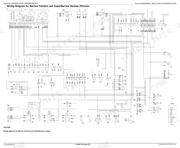
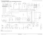
Yes. Section 240 (Electrical System - Operation and Tests, roughly 200 pages) has the wiring diagrams, component location drawings, and test procedures for the starting, charging, and lighting circuits. These are mechanical-era tractors on a 12-volt negative ground system - there are no fault codes to pull, so the diagrams plus a multimeter are how you chase electrical gremlins, and this book is where they live.
My battery will not charge, or the charge indicator glows with the engine running. Where do I look?
The manual's diagnosis lists the usual order: loose or corroded connections, a slipping or worn fan belt, a sulfated battery, low engine speed, then the alternator itself. Section 240 has the charging system output tests so you can measure whether the alternator is actually bad instead of swapping parts. Alternator removal and repair is in Section 40.
Does it cover injection pump and injector work?
Section 30 covers removal, installation, and timing of the fuel injection pump, plus nozzles, filters, and the air intake. Pump timing matters here - the diagnosis section lists an out-of-time injection pump as one cause of engine knock. Internal pump calibration is still a fuel shop job, but everything you can do on the tractor is in the book.
Which models and engines does this apply to - are the specs kept separate?
It covers the narrow 5310N (39 kW/53 hp), 5410N (53 kW/72 hp), and 5510N (59 kW/80 hp), 1997-2001. The 5310N and 5410N share the 2.9L block; the 5510N runs the longer-stroke 4.5L. Where they differ - oil capacity, hydraulic pump displacement, flow rates - the manual lists each model's numbers separately, so you are not guessing which spec is yours.