

Part of the John Deere Repair Manuals.
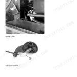
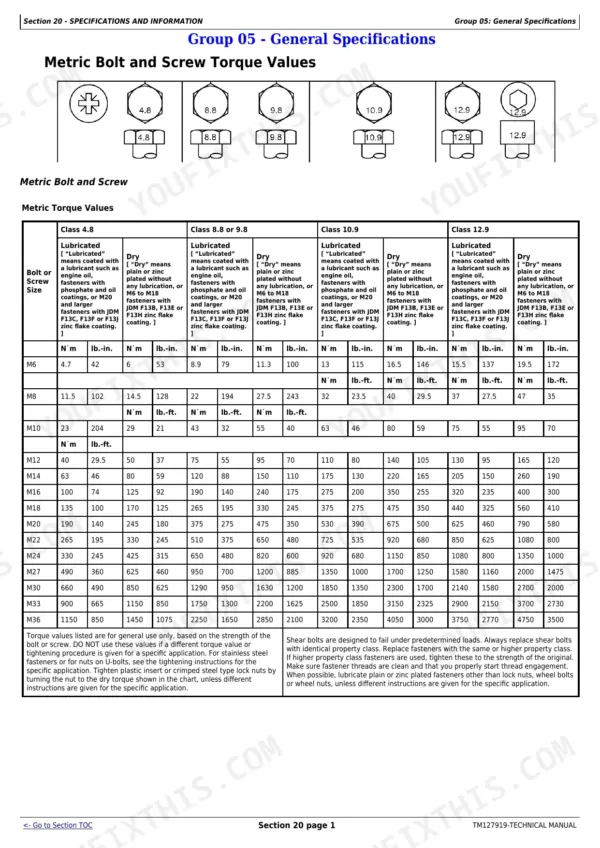
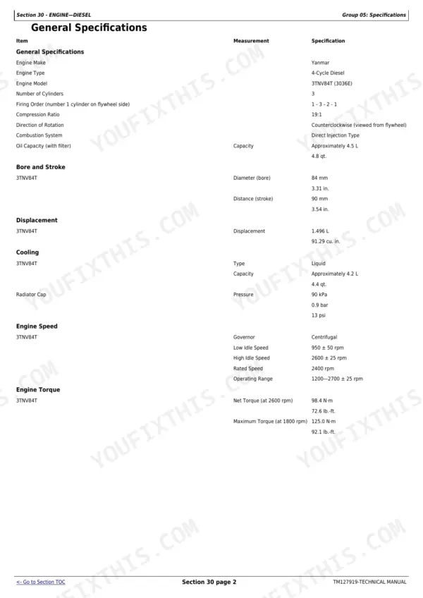
Need factory diagnostics for your John Deere 3032E, 3036E, or 3038E? This 865-page Diagnostic and Repair Manual PDF (OEM #TM127919) walks you through the diesel engine, power train, hydraulics, steering, and brakes on these compact utility tractors. Inside: full wiring schematics with connector pinouts, hydraulic schematics, exploded views, and a complete diagnostic trouble code section covering both the instrument cluster and engine control unit. You also get ECU programming and calibration steps, factory test values, and page after page of step-by-step repair procedures. Confirm the thermostat starts opening between 69.5 and 72.5 degrees C, then torque the hydraulic oil line rear fitting to 40-57 N-m (30-43 lb.-ft.). No more chasing an intermittent electrical fault with a test light and a hunch. Bookmarked with a real text layer; search any spec by keyword, pull it up on your phone in the shop, and get wrenching.
What's Inside This John Deere 3032E, 3036E, 3038E Manual
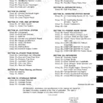
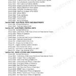
| System | Pages | Key Topics |
|---|---|---|
| Safety | 8-40 | Recognize Safety Information, Signal Words, Safety Decals, Servicing the Machine Safely, Handling Fuel and Fluids |
| Specifications and Information | 41-55 | General Machine Specifications, Fuel and Lubricants, Serial Number Locations |
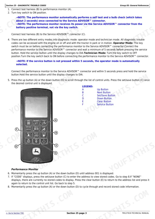
| Diagnostic Trouble Codes | 56-88 | Reading Codes, Instrument Cluster Control (Icc) Trouble Codes, Engine Control Unit (ECU) Trouble Codes |
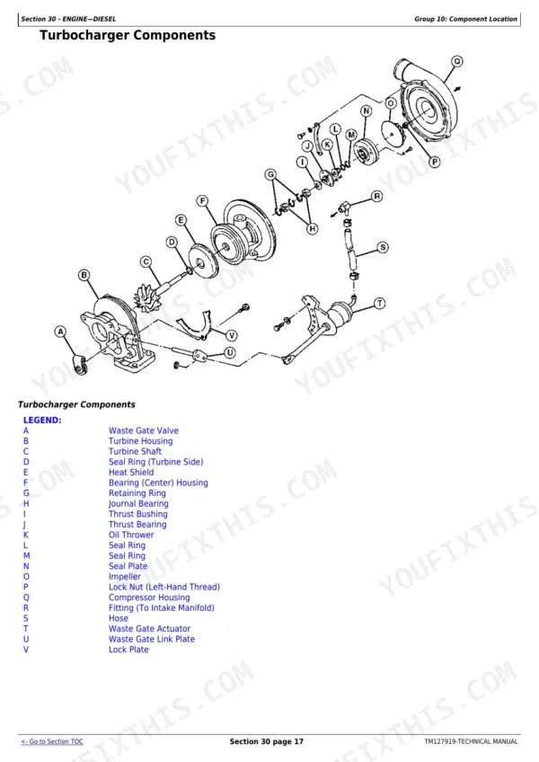
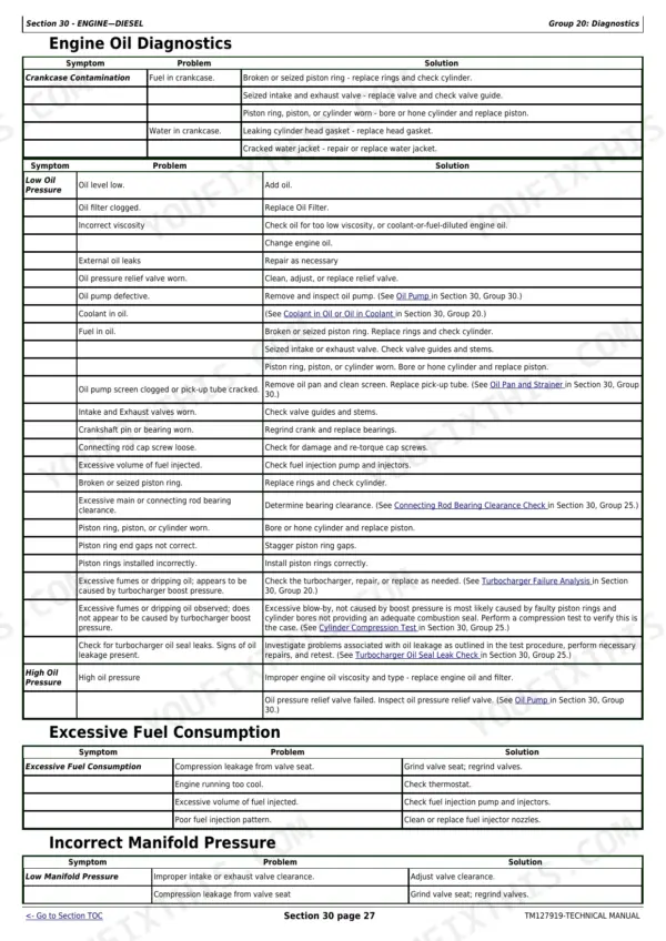
| Engine, Diesel | 89-272 | Engine Specifications, Air Cleaner and Intake Components, Fuel and Injection System, Cooling System, Theory of Operation, Diagnostics, Tests and Adjustments, Engine Repair and Overhaul |
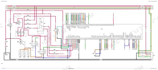
| Electrical | 273-392 | Battery, Alternator, Fuel Pump, Headlights and Turn Signals, Engine Oil Pressure Switch, Diesel Particulate Sensor, Instrument Cluster Control (Icc), Harnesses and Schematics, Circuit Tests and Repair |
| A - Electrical, 3036E | 393-550 | 3036E-Specific Component Locations, Wiring Harnesses and Schematics, Circuit Operation and Diagnostics |
| Electronic Control Units | 551-583 | ECU Theory of Operation, Programming and Calibrations, Tests and Adjustments, Diagnostic Addresses |
| Power Train | 584-742 | Drive Pedals and Linkage, Hydrostatic Transmission, Transmission Case, Differential and Final Drives, PTO, MFWD Front Axle, Diagnostics and Tests |
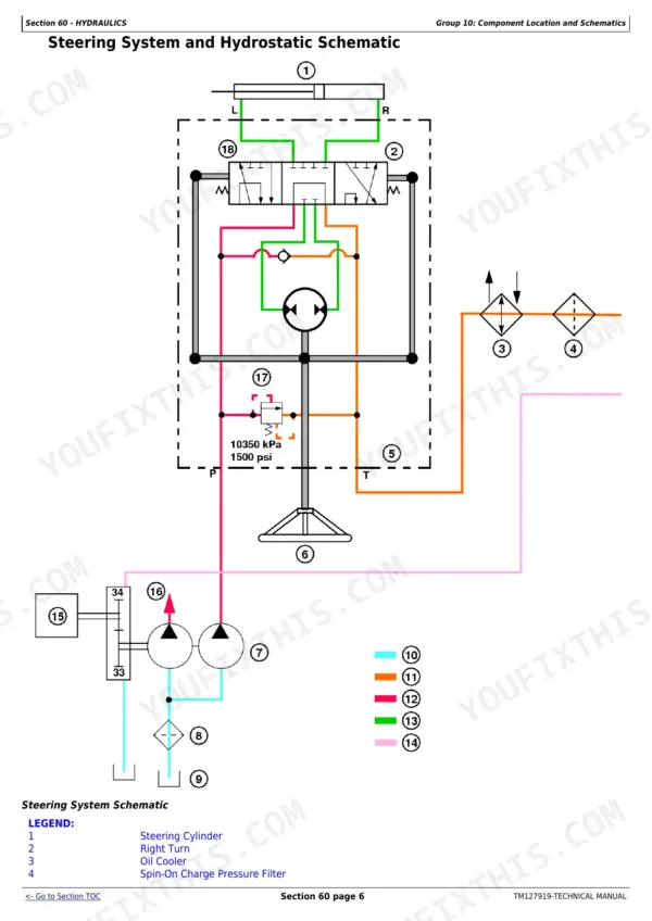
| Hydraulics | 743-810 | Gear Pump, Rockshaft and Lift Cylinder, Control Valve, Hydraulic Schematics, Pressure Tests (Main PTO and Implement Circuits), Torque Specifications |
| Steering | 811-830 | Steering Cylinder and Hoses, Steering Valve, Toe-In Setting, Diagnostics, Tests and Adjustments, Repair |
| Brakes | 831-851 | Brake Pedals and Linkage, Wet Disk Brakes, Brake Adjustment, Diagnostics and Repair |
| Miscellaneous | 852-865 | Operator Station and Seat, Hood and Body Panels, Wheels and Tires, Loader and Attachment Mounting |
Quick Reference Specifications
| Specification | Value | Page |
|---|---|---|
| Gear pump to gear housing cap screw torque | 63 N·m (46.5 lb-ft) | p. 745 |
| Gear to gear pump tapered shaft nut torque | 50 N·m (37 lb-ft) | p. 745 |
| Rockshaft cylinder head cap screw torque | 80 N·m (60 lb-ft) | p. 745 |
| Rockshaft to transmission case cap screw torque | 55 N·m (40 lb-ft) | p. 745 |
| Control valve hydraulic line torque | 40-57 N·m (30-43 lb-ft) | p. 745 |
| Implement circuit test gauge range | 34 473 kPa (5000 psi) | p. 745 |