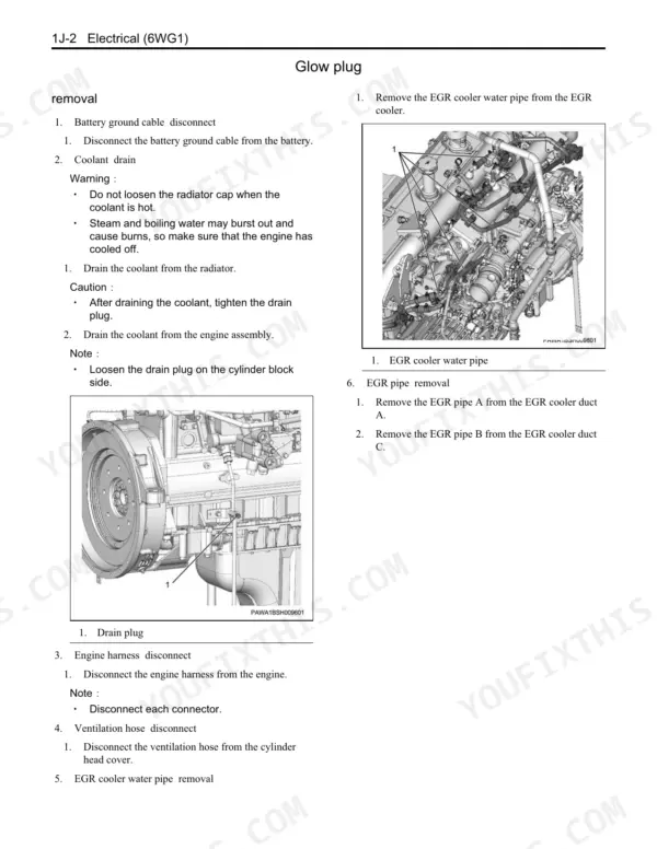
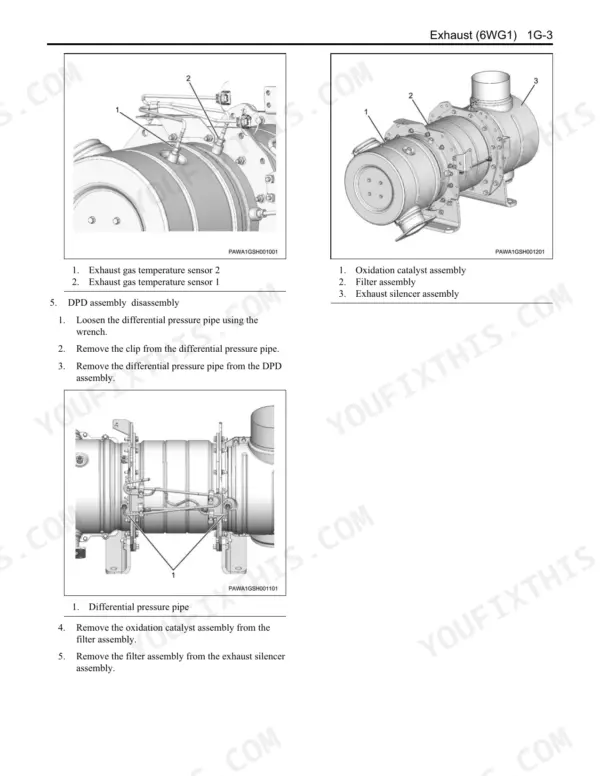
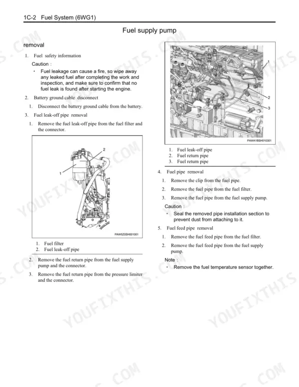
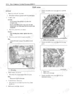
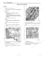
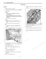
Torquing the cylinder head on a 6WG1 takes six steps. The M18 bolts go to 177 N·m, then 245 N·m, then 60 to 90 degrees of angle, finishing at 324 N·m. This Kawasaki 95Z7 / 115Z7 engine shop manual gives that sequence and the bolt order.
It combines two books in the July 2012 edition. Book 93215-00620 covers general information and troubleshooting: blink-count DTCs, common rail, EGR, DPD regeneration and the engine control wiring diagram. Book 93215-00630 covers removal, disassembly, inspection and reassembly of the Interim Tier 4 6WG1. It applies to Serial No. 97J1-5001 and up and 11J1-5001 and up.
Valve clearance is 0.4 mm on intake and exhaust, set cold with a feeler gauge between the rocker arm and camshaft. That lets you close up the head and valve train to the book's own numbers.
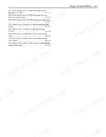
What's Inside This Manual
| System | Pages | Key Topics |
|---|---|---|
| Introduction | 1-7 | Safety Information for Repair Work, Engine Stand Use, Electrical System Precautions |
| Service Information Guide | 8-27 | How to Use the Manual, Standard Bolt and Nut Tightening Torques, Thread Locking Agents |
| Maintenance Information | 28-93 | Primary Specifications, Engine Control System, Fuel, Cooling, Lubrication, EGR, Preheat QOS, DPD, Functional Checks |
| Functional Inspection | 94-111 | OBD System Check, Diagnostic Light, Engine Control Checks |
| Symptom | 112-127 | Start Failure, Stalling, Rough Idle, White and Black Smoke, Noise, Fuel and Oil Consumption, Low Output, DPD Regeneration |
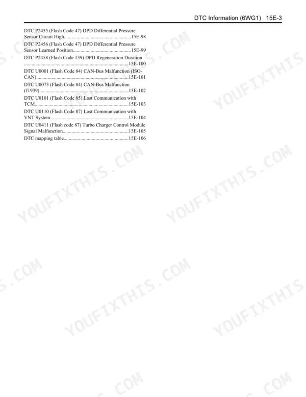
| DTC Information | 128-237 | Diagnostic Trouble Codes with Flash Codes, Detection Conditions and Diagnostic Procedures |
| Engine Control | 238-361 | ECM, Sensors, Injectors, Common Rail, Circuit Checks |
| Wiring Diagram | 362-396 | Engine Control Wiring Diagram, Connector Location, Connector List, Terminal Names |
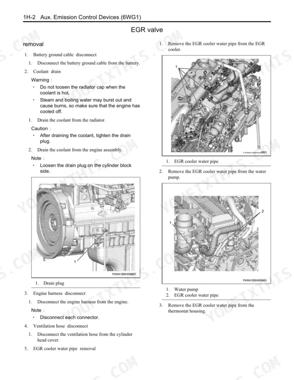
| Mechanical | 397-761 | Removal, Installation, Disassembly, Reassembly and Inspection: Cylinder Head, Valves, Pistons, Crankshaft, Timing Gears |
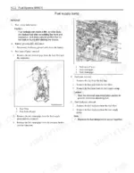
| Fuel System | 762-821 | Fuel Pipes, Common Rail, Supply Pump, Injectors, Fuel Filter |
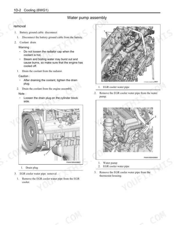
| Cooling | 822-853 | Water Pump, Thermostat, Coolant Pipes |
| Lubrication | 854-901 | Oil Pump, Oil Cooler, Oil Filter, Oil Thermo Valve |
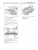
| Induction | 902-919 | Turbocharger, Intake Ducts |
| Exhaust | 920-933 | Exhaust Manifold and Pipes, Exhaust Sensors |
| Aux. Emission Control Devices | 934-955 | EGR Cooler, EGR Valve, Emission Control Parts |
| Electrical | 956-993 | Starter, Generator, Glow Plugs, Tightening Torque Views |
Quick Reference Specifications
| Specification | Value | Page |
|---|---|---|
| Engine type | Diesel/4-cycle/water-cooled, inline 6-cylinder OHC | p. 32 |
| Cylinder bore x stroke | 147 mm {5.78 in} x 154 mm {6.06 in} | p. 32 |
| Displacement | 15.681 L {956.85 cu·in} | p. 32 |
| Compression ratio | 16.5 | p. 32 |
| Compression pressure | 2940 kPa { 30 kgf/cm2 } /200 r/min | p. 32 |
| Rated output | 397 kW { 540 ps } /1800 r/min | p. 32 |
| Maximum torque | 2250 N · m { 229 kgf · m } /1500 r/min | p. 32 |
| Dry weight | 1150 kg { 2535 lb } | p. 32 |
| Fuel injection order | 1, 5, 3, 6, 2, 4 | p. 32 |
| Valve clearance (intake and exhaust, cold) | 0.4 mm { 0.0157 in } While cool | p. 32 |
| Injection pump type | Electronic control common rail type | p. 32 |
| Turbocharger type | RHG8V {IHI} | p. 32 |
| Engine oil level | 42 to 57 L { 11 to 15 US gal / 9 to 13 Imp.gal } Reference value | p. 32 |
| Oil pan capacity | 37 to 52 L { 10 to 14 US gal / 8 to 11 Imp.gal } | p. 32 |
| Volume of coolant in engine | 36.0 L { 10 US gal / 8 Imp.gal } | p. 32 |
| Thermostat opening temperature | 76.5 °C { 170 °F } | p. 33 |
| Thermostat full-open temperature / lift | 90 °C { 194 °F } /11 mm (0.43 in) | p. 33 |
| Generator nominal output | 24 V - 50 A | p. 33 |
| Starter output | 24 V /7.0 kW | p. 33 |
| Oil pump discharge pressure | 0.54 MPa { 6 kgf/cm2 / 78 psi } | p. 34 |