
Steering valve, stop valve, gear pump and the boom and bucket cylinders take up roughly a quarter of this Kawasaki 95ZIV shop manual PDF, a 462-page factory book (OEM ID AAA-S97C2E14-962) for the wheel loader that also tears down the torque converter, transmission, axles and differential. Before any of that, the early chapters show you how to pull the deck, tanks, engine room, cab, floor board and boom, then service the center pin at the articulation joint. Brake valve, hydro-master and disc brake service follow, with troubleshooting tables at the back. Keep linkage pin clearance between 0.120 and 0.295 mm (0.0047 and 0.0116 in.), and torque the gear pump retainer bolts to 9.6 kg-m (69 lb-ft). A made-up pump bolt torque comes back as a leak. Bookmarks put you on the right group in a click or two, and a text search lands on your spec in seconds.
What's Inside This Kawasaki 95ZIV Manual
| System | Pages | Key Topics |
|---|---|---|
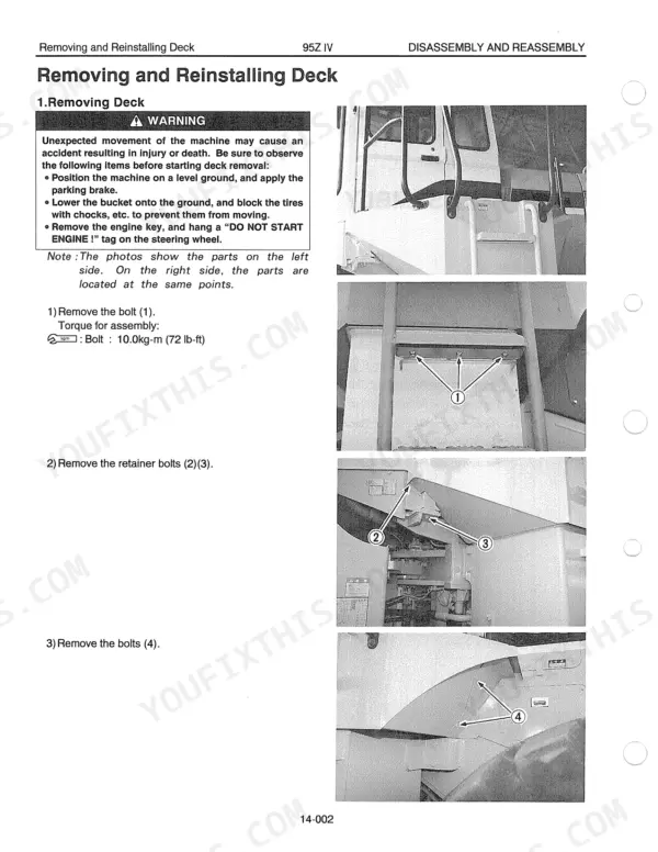
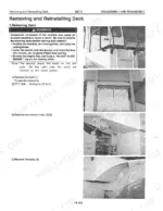
| Removing and Reinstalling Deck | 14-15 | Deck, Hand Rail, Retainer Bolts, Hose Band |
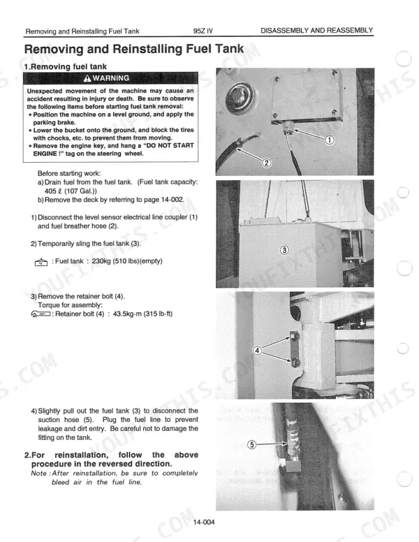
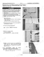
| Removing and Reinstalling Fuel Tank | 16 | Level Sensor, Fuel Breather Hose, Fuel Tank, Retainer Bolt, Suction Hose |
| Removing and Reinstalling Hydraulic Tank | 17-18 | Hydraulic Tank, Unloader Valve, Suction Pipe, Window Washer Liquid Tank, Hose |
| Removing and Reinstalling Engine Room | 19-23 | Engine Room, Radiator Guard, Condenser, Brake Oil Tank, Accumulator, Roof |
| Removing and Reinstalling Cab | 24-25 | Cab, ROPS Canopy, Wiper Motor, Air Conditioner Cover, Cab Retainer Bolt |
| Removing and Reinstalling Cab and Floor Board | 26-30 | Cab, Floor Board, Accelerator Control Cable, Air Conditioner Lines, Heater Hoses, Accumulator |
| Removing and Reinstalling Boom | 31-34 | Boom, Bucket, Link, Lever, Boom Cylinders, Grease Hose |
| Center Pin | 35-36 | Bearing Cover, Shim, Grease Nipple, Bearing Outer Ring |
| Disassembly & Reassembly: Center Pin | 37-42 | Center Pin Removal, Center Pin Reinstallation, Articulation Stopper, Dust Seal |
| Service Standards: Linkage | 43-50 | Linkage Pin Clearance, Bucket Positioner, Boom Kick-Out |
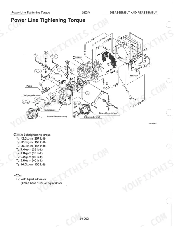
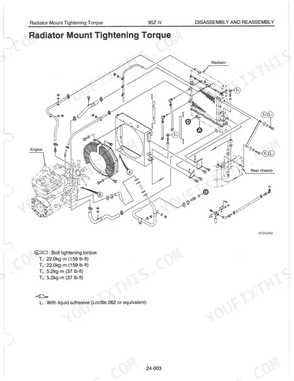
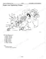
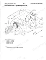
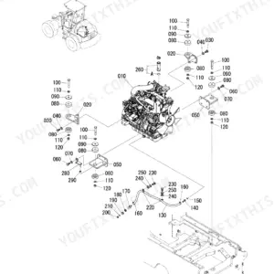
| Power Group: Disassembly & Reassembly | 51-130 | Radiator Removal, Engine Removal, Propeller Shaft, Axle Assembly, Differential Assembly |
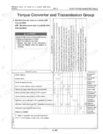
| Torque Converter & Transmission Group | 131-214 | Torque Converter, Transmission Assembly, Clutch Assembly, Control Valve |
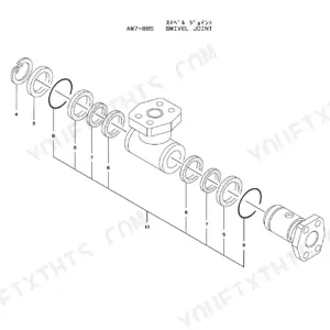
| Hydraulic Group | 215-330 | Gear Pump, Steering Pilot Valve, Steering Valve, Stop Valve, Boom Cylinder, Bucket Cylinder |
| Brake Group & Troubleshooting | 331-462 | Brake Valve, Hydro-Master, Accumulator, Disc Brake, Troubleshooting Tables |
Quick Reference Specifications
| Specification | Value | Page |
|---|---|---|
| Gear pump retainer bolt torque | 9.6kg-m (69 lb-ft) | p. 231 |
| Gear pump (3) retainer bolt torque | 9.6kg-m (69 lb-ft) | p. 232 |
| Joint section between bucket and boom standard clearance | 0.120~0.295 mm (0.0047~0.0116 in.) | p. 45 |
| Joint section between boom and lever standard clearance | 0.120~0.295 mm (0.0047~0.0116 in.) | p. 45 |
| Engine oil quantity | 43 L (11.4 gal.) | p. 83 |
| Bolt (11) torque for brake drum | 13.5kg-m (98 lb-ft) | p. 167 |
| Bolt (13) torque for parking brake | 22.0kg-m (159 lb-ft) | p. 166 |
| Solenoid nut (7) tightening torque | 1.0kg-m (7.2 lb-ft) | p. 207 |
| Spool (9) tightening torque | 4.0kg-m (29 lb-ft) | p. 207 |
| Bucket positioner clearance | 5 ± 2mm (0.12~0.27 in.) | p. 277 |
| Clearance between chassis and steering cylinder | 1.2mm or less | p. 280 |
| Fuel tank capacity | 405 L | p. 16 |
Kawasaki 95ZIV Common Problems This Manual Covers
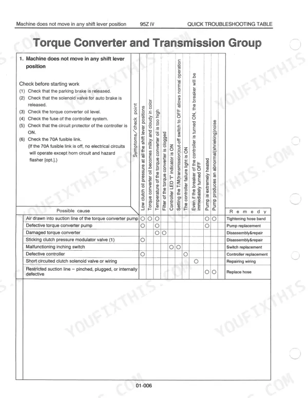
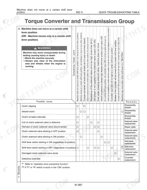
Kawasaki 95ZIV wheel loader does not move at a certain transmission shift lever position
Block the machine securely and stay clear of the articulation area and wheels whenever the engine runs during this test (page 431). Check each shift lever position against the chart on that page. If the transmission comes out, inspect the strainer and filter. A small amount of contamination means the T/C oil cooler can stay in place. A large amount means you remove the cooler too (page 145).
Manual Section: Torque Converter and Transmission Group Troubleshooting p. 431Boom cylinder or bucket cylinder shows excessive cylinder drift while holding the boom and bucket
Measure the drift rate using the method the page 442 chart specifies before you condemn a cylinder, and keep clear of fittings because trapped oil under pressure can spray out. Before pulling a bucket cylinder, chock the tires, set the boom and bucket on the ground, and relieve internal pressure from the loading line and the hydraulic tank (page 275). Work from a step and never stand on the machine.
Manual Section: Hydraulic Group Troubleshooting p. 442Brake accumulator pressure reads low or the brake buzzer sounds on the wheel loader
Check brake oil level and accumulator pressure using the Brake Group Troubleshooting chart. Verify the accumulator nitrogen charge against 30 kg/cm² at 20°C (page 361), and use the charging valve setup shown on page 360. Improper gas pressure can cause serious injury or death, so never guess at the charge.
Manual Section: Brake Group Troubleshooting p. 361Electrical system engine does not start when the starter key is turned in the cab
Chock the wheels securely and never try to start the machine from the ground, because it may start and move suddenly during testing (page 456). Work through the engine start checks in the Electrical Group Troubleshooting chart. When you read the instrument panel, remember that the lamp test checks only the red warning lamps, not the green or amber ones (page 458).
Manual Section: Electrical Group Troubleshooting p. 456Boom, bucket, lever and link pin joints show clearance beyond the linkage service standard
Measure pin clearance at every loader joint, including bucket to boom, boom to lever, boom to boom cylinder and front chassis to boom, against 0.120 to 0.295 mm (page 45). Steering cylinder joints have a tighter standard of 0.100 to 0.250 mm. Work from a step, ladder or platform, because standing on a tire, the boom or the linkage can cause serious injury (page 277).
Manual Section: Service Standards: Linkage p. 45Steering cylinder joint at the chassis shows excess clearance after cylinder repair or replacement
Measure the clearance between the chassis and the steering cylinder and set it to 1.2 mm or less (page 280). Bleed air from the cylinder at low idle by stroking the piston 4 to 5 times. If you skip this, the piston seal or backup ring may seize. Keep everyone out of the articulation area while you turn the wheel with the engine running, and never start the engine with someone in that area.
Manual Section: Hydraulic Group p. 280Frequently Asked Questions
How do I troubleshoot an engine that is hard to start or will not start?
Before testing, ensure the transmission shift lever is in 'NEUTRAL'. Check for a blown or removed fusible link, a blown or removed diode pack (Cummins), or a defective battery relay, neutral relay, starter motor, or starter switch. Also, ensure the battery is charged and check for loose or corroded starting circuit connections. If the engine oil is too thick for cold weather, change the oil to a lower viscosity. p. 456
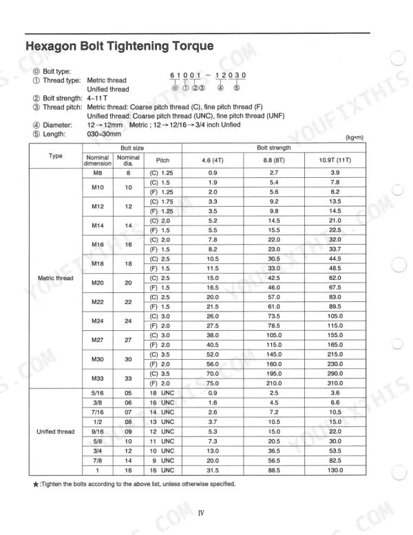
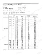
What are the torque specifications for the hexagon bolts used on the Kawasaki 95ZIV wheel loader?
The tightening torque for hexagon bolts depends on the bolt size, thread pitch, and bolt strength (4.6, 8.8, or 10.9T). For example, an M10 bolt with a 1.5 pitch and 8.8 strength requires 5.4 kg-m of torque, while an M20 bolt with a 2.5 pitch and 10.9T strength requires 62.0 kg-m of torque. p. 6
What is the procedure for bleeding air from the hydraulic cylinder after repair?
After repairing or replacing a cylinder, operate the engine at low-idling speed and cycle the cylinder piston for 4 to 5 strokes, stopping about 100mm (4.0 in.) before both stroke ends. Then, operate the cylinder piston to both stroke ends 4 to 5 times. Finally, add hydraulic oil to the tank and check the cylinder and piping for oil leakage. p. 273
What is the standard piston stroke for the 2nd, 3rd, low, and reverse clutches?
The standard piston stroke for the 2nd clutch is 2.0 ± 0.5mm (0.0787 ± 0.0196 in.), for the 3rd clutch is 2.5 ± 0.5mm (0.0984 ± 0.0196 in.), for the low clutch is 3.5 ± 0.5mm (0.1378 ± 0.0196 in.), and for the reverse clutch is 3.5 ± 0.5mm (0.1378 ± 0.0196 in.). p. 178
What is the pilot relief valve setting pressure on the Kawasaki 95ZIV wheel loader?
The relief valve setting pressure for the pilot relief valve unit is 36 ± 3 kg/cm² (512 ± 43 psi) at low idle. The reducing valve setting pressure is 15 ± 3.5 kg/cm² (213 ± 50 psi) at engine stop. p. 300
How will I receive this Kawasaki 95ZIV Shop Manual?
You download the Shop Manual yourself: 462 pages, searchable PDF, available immediately. Keep a copy on every device you use.
Am I able to print pages from this Kawasaki 95ZIV manual?
Yes. Print the pages or sections you need for your own shop use. Any standard printer works.


Reviews
There are no reviews yet.