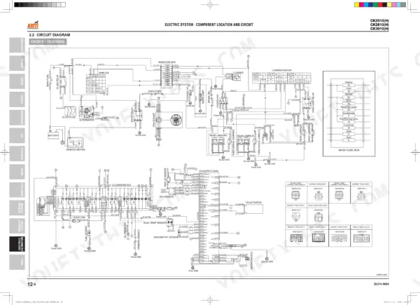
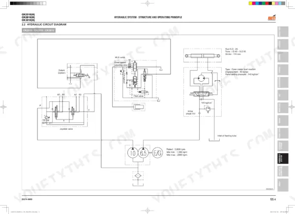
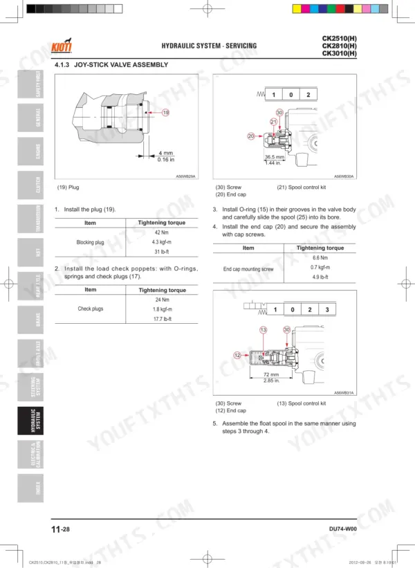


This is the factory Kioti workshop manual for the CK2510(H), CK2810(H), and CK3010(H) compact tractors, built around the 3A139 diesel engine. It runs 412 pages, carries a full searchable text layer, and covers both the mechanical and HST driveline variants of these machines.
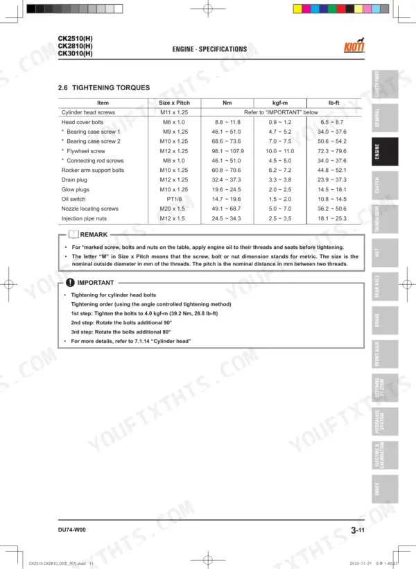
Inside you get the procedures Kioti service technicians rely on: engine teardown, clutch and transmission service, HST diagnosis, front axle and steering repair, hydraulic circuit work, and the complete electrical system with wiring diagrams. Torque values, clearances, and maintenance intervals are called out throughout.
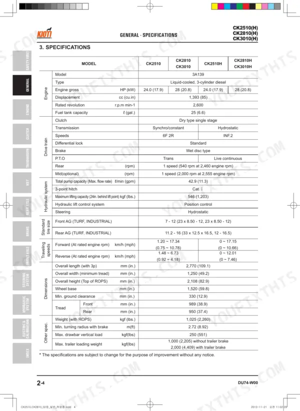
Whether you are chasing a no-start, servicing the HST, or rebuilding a system yourself, this manual gives you the identification, specifications, and step-by-step removal and installation detail to finish the job and confirm it against factory numbers.
What's Inside This Manual
| System | Pages | Key Topics |
|---|---|---|
| General | 19-48 | Tractor Identification, Lubricants, Fuel and Coolant, Tightening Torque, Maintenance Schedule, Tires |
| Engine | 49-146 | Engine Identification, Lubricating System, Cooling System, Fuel System, Governor System |
| Clutch | 147-160 | Clutch Pedal Play Adjustment, Clutch Disc Wear, Pressure Plate Flatness, Operation Principle, Disassembling and Assembling |
| Transmission | 161-200 | Power Train Diagram, Main Gear Shift Section, Differential Gear, Servicing, Troubleshooting |
| HST | 201-226 | Operating Principle (Power Train Diagram, Structure, Functions of Each Component, Operation Control), Servicing (Exploded View, Disassembly, Assembly, HST Pedal) |
| Rear Axle | 227-238 | Power Train, Differential Lock System, Differential System, Servicing, Troubleshooting |
| Brake | 239-250 | Operating Principle, Features Of Wet Disc Brakes, Inspection For Overhaul |
| Front Axle | 251-272 | Front Axle Structure, Wheel Alignment, Measurement and Adjustment, Differential System, Troubleshooting |
| Steering System | 273-298 | Hydraulic Schematic, Steering Cylinder, Gear Pump, Hydraulic Circuit Diagram, Operation Principle |
| Hydraulic System | 299-342 | Hydraulic Scheme, Oil Filter, Joystick Valve, Auxiliary Control Valve, 3 Point Hitch Lifting System, Hydraulic Circuit Diagram |
| Electric System | 343-404 | Legend for Circuit Diagram, Electric Component Location, Pre-Heating, Post-Heating, Manual Heating, Starting, Charging, Lighting |
| Index | 405-412 |
Every system also includes specifications.
Quick Reference Specifications
| Specification | Value | Page |
|---|---|---|
| Rear wheel bolt torque | 215 Nm (22 kgf-m, 160 lb-ft) | p. 32 |
| Front wheel mounting nuts torque | 62.8 ~ 72.5 Nm (6.4 ~ 7.4 kgf-m, 46.3 ~ 53.5 lbs-ft) | p. 262 |
| Air cleaner element replacement interval | Once yearly or after every sixth cleaning, whichever comes first | p. 33 |
| Fuel filter element replacement interval | Every 200 hours | p. 27 |
| Engine oil filter replacement interval | Every 200 hours | p. 27 |
| Hydraulic oil filter replacement interval | Every 200 hours | p. 27 |
| Grease fittings lubrication interval | Every 50 hours | p. 31 |
| Battery condition check interval | Every 100 hours | p. 27 |
| Battery voltage | More than 12 Volt | p. 378 |
| Starter relay non-energized continuity | No continuity between terminals 87 and 30 | p. 381 |
| Starter relay energized continuity | Continuity between terminals 87 and 30 | p. 381 |
| Clutch pedal safety switch clearance | 0.5 ~ 1.0 mm (0.0197 ~ 0.039 in.) | p. 152 |