



This Kioti workshop manual covers the DS4110(HS) and DS4510(HS) tractors built from 2001 to 2010, powered by the 4A200 LWE and 4A220 LWE diesel engines rated at 41 and 45 HP. Its 486 pages document the engine, clutch, transmission, rear axle, brakes, front axle, steering, hydraulics, and electrical system, following the general specifications and safety chapters.
Each section carries exploded views, disassembly, service and assembly steps, and inspection and adjustment procedures, along with the specifications and tightening torques you need to put it back together correctly.
Whether you are tracking a no-crank fault, restoring hydraulic lift, or servicing the PTO, this manual gives the factory values and repair sequence rather than general advice. It downloads as a PDF you can read on any device or print for the workbench.
What's Inside This Manual
| System | Pages | Key Topics |
|---|---|---|
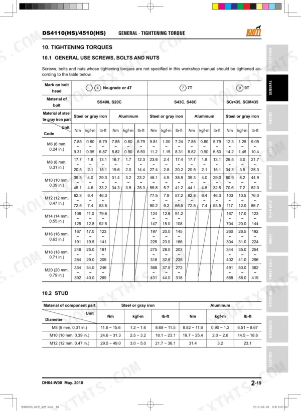
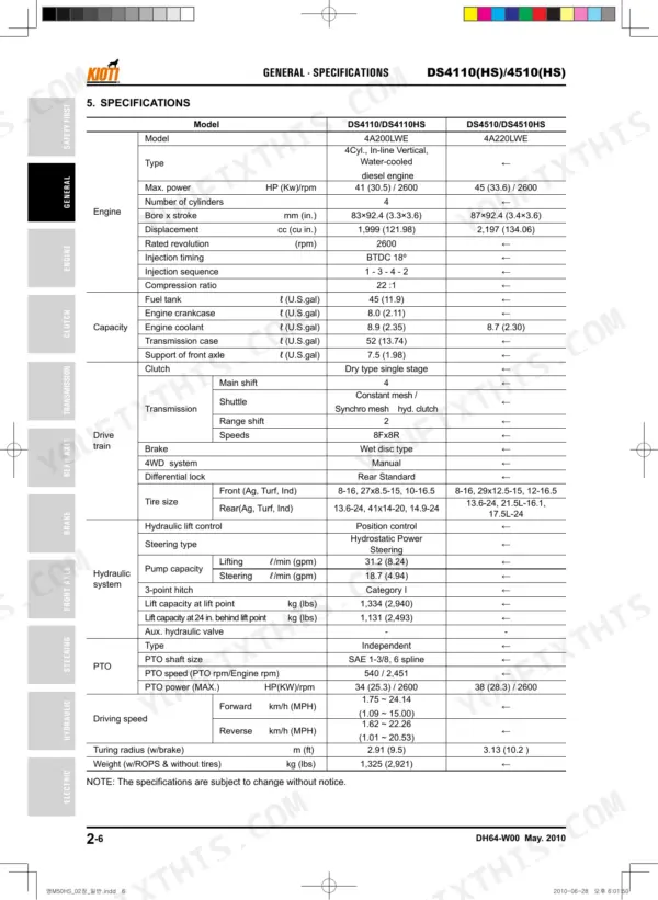
| General | 19-42 | Description for Symbols and Abbreviations, Tractor Appearance, Serial Number, Dimensions, Tightening Torques |
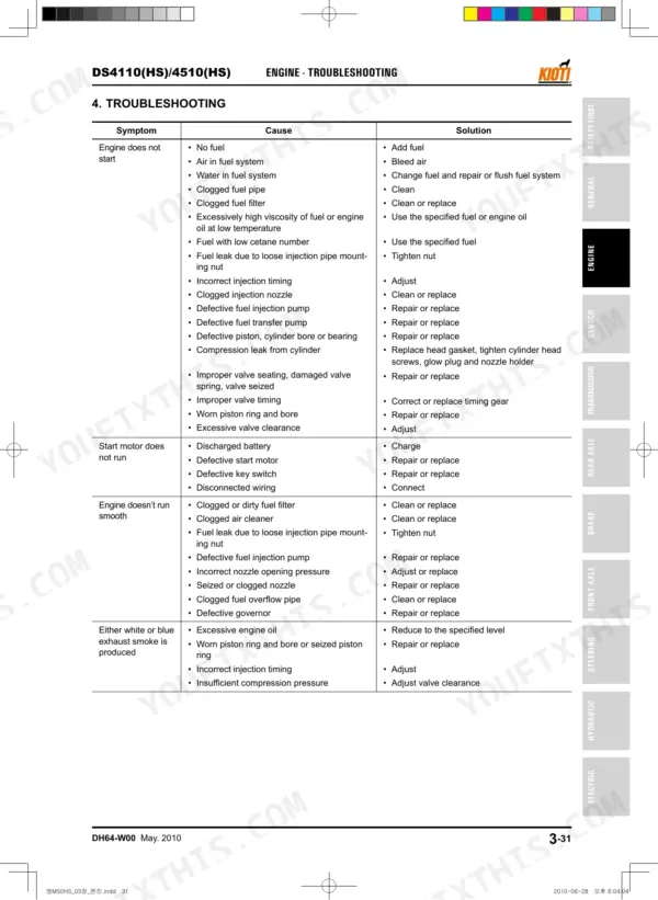
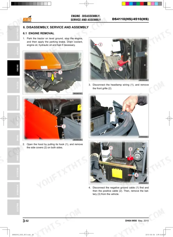
| Engine | 43-148 | General Information, Engine Exploded View, Inspection and Adjustment |
| Clutch | 149-164 | Disassembly and Assembly, Clutch Exploded View, Inspection and Adjustment |
| Transmission | 165-232 | Transmission Exploded View, Disassembly, Service and Assembly |
| Rear Axle | 233-258 | Rear Axle Exploded View, Disassembly, Service and Assembly, Inspection and Adjustment |
| Brake | 259-272 | Brake Exploded View, Disassembly, Service and Assembly, Inspection and Adjustment |
| Front Axle | 273-314 | Front Axle Exploded View, Disassembly, Service and Assembly, Inspection and Adjustment |
| Steering System | 315-344 | Steering Cylinder, Steering Unit, Structure And Function, Operating Diagram, Operating Principle, Steering Cylinder Internal Structure, Steering Unit Relief Pressure, Relief Pressure Setting |
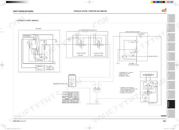
| Hydraulic System | 345-418 | Structure And Function, Components And Circuit Diagram, Operating Principle, Implement Section, Main Body Section, Hydraulic Components, Gear Pump, Oil Filter |
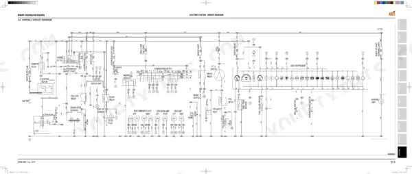
| Electric System | 419-478 | Location Of Electrical Devices, Circuit Diagram, Color Code Of Wire, Cross Section Of Wire, Symbols For Electric Components, Overall Circuit Diagram, HS Model, Operating Principle |
| Index | 479-486 |
Every system also includes specifications, structure and function, and troubleshooting.
Quick Reference Specifications
| Specification | Value | Page |
|---|---|---|
| Front axle cover mounting bolt (M8) | 23.5~27.5 Nm | p. 276 |
| Front axle case and front axle case support mounting bolt (M12) | 77.5~90.2 Nm | p. 276 |
| Front wheel bolt, nut (1) | 167 ~ 186 Nm | p. 36 |
| Rear wheel bolt, nut (2) | 275 ~ 319 Nm | p. 36 |
| Air cleaner element cleaning interval | every 50 hours or 3 months | p. 33 |
| Air cleaner element replacement interval | every 400 hours or 1 year | p. 33 |
| Engine oil filter replacement interval (initial) | initial 50 hours | p. 33 |
| Engine oil filter replacement interval (regular) | every 400 hours or 1 year | p. 33 |
| Hydraulic filter replacement interval (initial) | 50 hours after initial operation | p. 360 |
| Hydraulic filter replacement interval (regular) | every 400 hours of operation | p. 360 |
| Engine start relay type | 5P, 12V, 40~60A | p. 421 |


