When the machine will not travel, starts slow or feels weak, this book traces the fault down to a stuck main poppet or a loose adjusting screw. It is the service manual for the Kobelco ED150 Blade Runner (Acera SR) excavator-dozer and its D04FR-TAA engine.
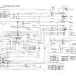
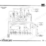
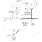
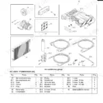
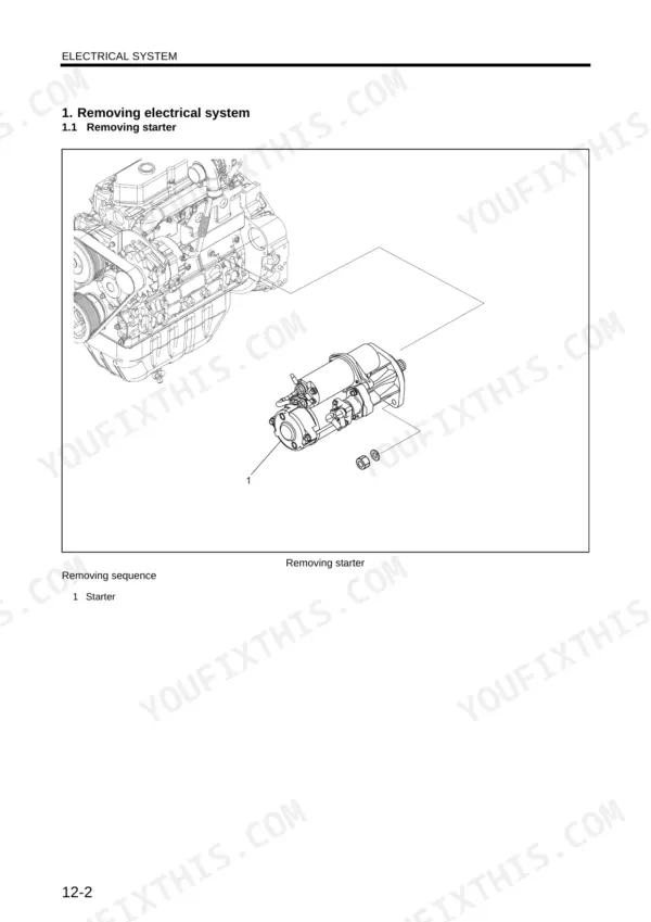
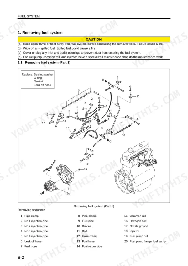
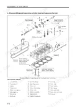
It covers the mechatro control, hydraulic, electric and air conditioning systems. It also covers teardown of the attachments, upper structure and travel system. The engine half goes through basic engine overhaul, then fuel, lubrication, cooling, inlet and exhaust. If you are changing a thermostat, the book gives the opening point as 71 ± 2°C [160 ± 3.6°F].
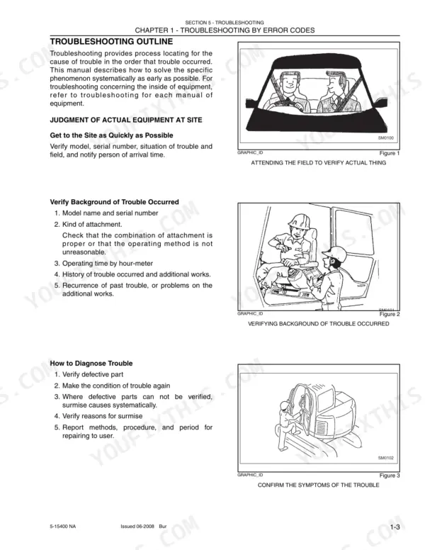
Troubleshooting is split three ways: by error code, by trouble symptom and through service diagnosis mode.
What's Inside This Kobelco ED150 Manual
| System | Pages | Key Topics |
|---|---|---|
| Safety and General Information | 1-49 | General Precautions for Making Repairs, Machine Specifications, Attachment Dimensions |
| Maintenance | 50-121 | Tools, Standard Maintenance Time Table, Maintenance Standards and Test Procedures |
| Systems | 122-449 | Mechatro Control System, Hydraulic System and Hydraulic Circuit Diagram, Electric System, Components, Air Conditioning |
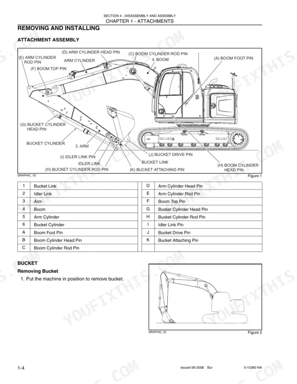
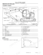
| Disassembly and Assembly | 450-753 | Attachments, Upper Structure, Travel System |
| Troubleshooting | 754-871 | Troubleshooting by Error Codes, By Trouble Symptom and by Service Diagnosis Mode |
| Engine: Introduction and General | 872-905 | Engine D04FR-TAA Identification, General Precautions, Main Specifications |
| Engine: Service Data, Tools and Overhaul | 906-927 | Service Data, Service Tools, Determination of Overhaul |
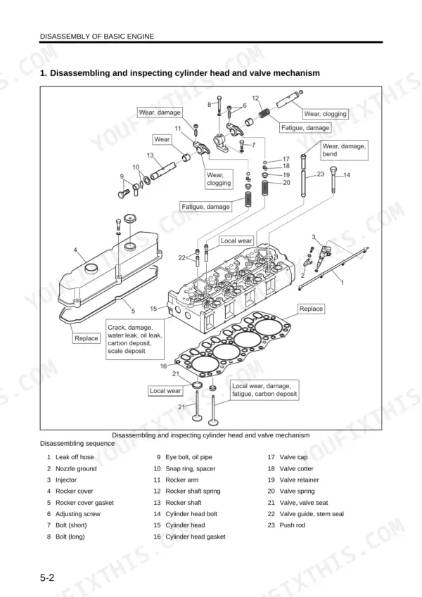
| Basic Engine | 928-989 | Disassembly, Inspection and Repair, Reassembly of the Basic Engine |
| Engine Fuel, Lubrication, Cooling, Inlet and Exhaust | 990-1017 | Fuel System, Lubrication System, Cooling System, Inlet and Exhaust System |
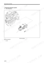
| Engine Electrical System | 1018-1051 | |
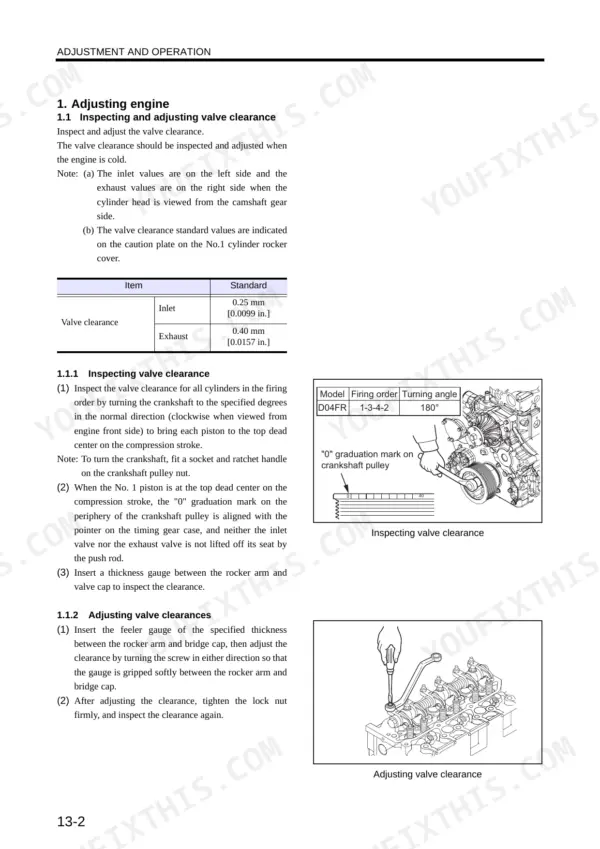
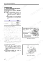
| Engine Adjustment, Operation and Troubleshooting | 1052-1096 | Adjustment and Operation, Break-In, Engine Troubleshooting |
Quick Reference Specifications
| Specification | Value | Page |
|---|---|---|
| Engine type | Water cooled, 4 cycle diesel engine, turbocharged | p. 902 |
| No. of cylinders - arrangement | 4 cylinder in-line | p. 902 |
| Combustion system | Direct injection | p. 902 |
| Cylinder bore × stroke | 102 x 130 mm [4.02 × 5.12 in.] | p. 902 |
| Displacement | 4.249 L [259 cu. in.] | p. 902 |
| Compression ratio | 17.8 | p. 902 |
| Firing order | 1-3-4-2 | p. 902 |
| Direction of rotation | Counterclockwise when viewed from flywheel side | p. 902 |
| Dry weight | Approx. 395 kg [870.8 lbs] | p. 902 |
| Fuel system type | Common rail fuel injection system | p. 902 |
| Fuel system model number | CP1H | p. 902 |
| Engine oil classification | API classification CF-4 or above class | p. 903 |
| Engine oil total capacity (including oil filter) | 17.5 L [4.62 US gallons] | p. 903 |
| Relief valve opening pressure | 0.35 ± 0.05 MPa {3.5 ± 0.5 kgf/cm²} [50 ± 7 psi] | p. 903 |
| Coolant capacity (Engine water jacket) | 6 L [1.6 US gallons] approx. | p. 903 |
| Thermostat valve opening temperature | 71 ± 2°C [160 ± 3.6°F] | p. 903 |
| Turbocharger model number | TD04HL | p. 903 |
| ECU model number | EDC16UC40 | p. 903 |
| Starter output | 24V - 5kW | p. 904 |
| Alternator output | 24V - 50A | p. 904 |
Kobelco ED150 Common Problems This Manual Covers
Machine will not travel, travels slowly or lacks power
Start with the main relief valve. Check for foreign matter between the main poppet and seat, a sticking poppet, a broken or deformed spring, a clogged poppet throttle and a loose adjusting screw. Then read pump pressure. Low P1 means the right travel motor relief valve has failed, and low P2 means the left one.
Manual Section: Disassembly and Assembly p. 602Air trapped in the hydraulic pump after it has been removed and refitted
The pump installation sequence has a dedicated step (step 15) for bleeding air out of the pump. You do it by loosening the drain port (Dr) so the trapped air can escape. Do this before you put the pump under working load so it is not run with air in it.
Manual Section: Disassembly and Assembly p. 523Too much black smoke while the engine is working
The manual treats heavy black smoke as a sign that the engine is overloaded, and the instruction is to reduce the load on the engine immediately. During break-in, also check the smoke color and any odors. If anything looks abnormal, stop the engine, find the cause and take appropriate measures before running it again.
Manual Section: Engine Adjustment, Operation and Troubleshooting p. 891Starter seizing or flat battery after long cranking
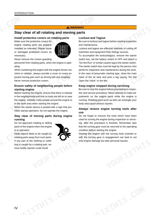
The engine operation section warns against cranking continuously. Holding the starter on drains the battery and can make the starter seize. Crank in short bursts instead of holding the key. If the engine still will not fire, stop cranking and look for the cause rather than wearing out the starter and batteries.
Manual Section: Engine Adjustment, Operation and Troubleshooting p. 892Frequently Asked Questions
How do I get the ED150 into service diagnosis mode?
Hold the buzzer stop switch down and turn the starter key switch on. The service diagnosis mode screen comes up. The separate diagnostic mode is reached by selecting DIAGNOSTIC from the main menu screen and pressing the ENTER key. p. 154
I fixed the sensor but the error is still on the panel. How do I clear it?
After you correct a sensor failure, switch the panel ON/OFF switch from OFF to ON and the error indication releases. The travel alarm fault R154 works differently. It returns to normal when the power is turned OFF. p. 445
Why won't it travel, or why is travel slow and weak?
The book points at the main relief valve first. Look for foreign matter between the main poppet and seat, a sticking poppet, a broken or deformed spring, a clogged poppet throttle or a loosened adjusting screw. Pump pressure tells you which side has the problem. Low P1 means the right travel motor relief valve has failed, and low P2 means the left one has. p. 602
How much boom and arm drift is acceptable?
The book allows 3 mm per 5 minutes on the boom cylinder at no load. The arm cylinder figure is 4 mm per 5 minutes. If the drift is more than that, look at the cylinders and valves before blaming the operator. p. 100
How do I chase a travel alarm fault on relay R-8?
Check travel alarm relay R-8 and replace it if it has failed. If the error cancels after you pull the relay, the relay unit is the problem. Otherwise, check the harness between CN-109F, CN2-2 and fuse and relay box E-1. That procedure is the reason to own the book, because it keeps you from throwing a controller at a wiring fault. p. 815