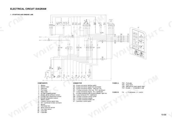
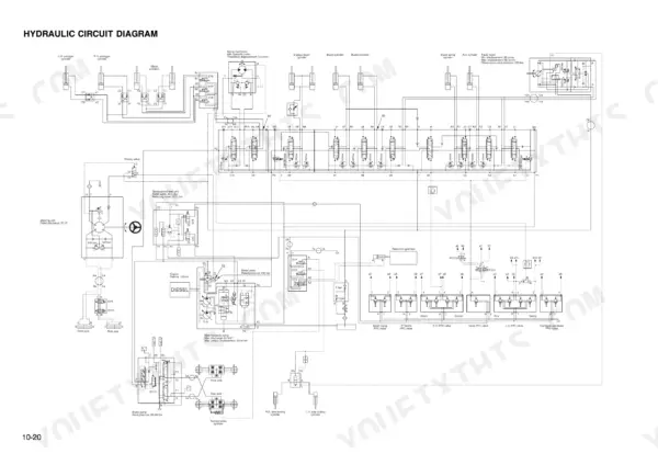
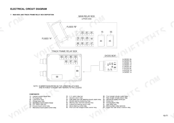
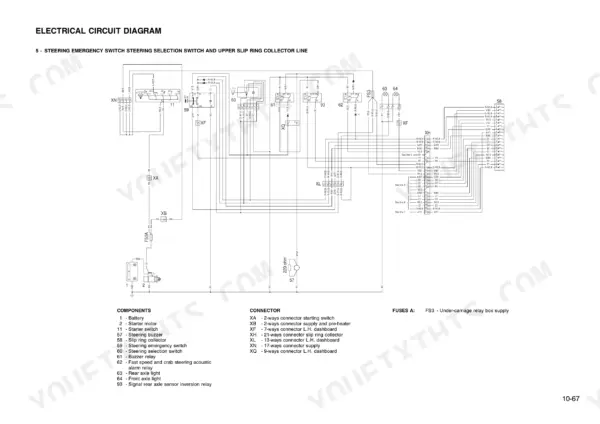
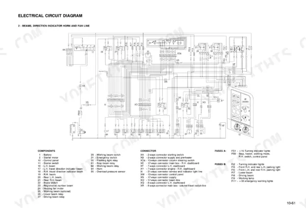
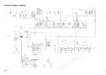
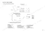
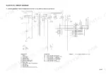
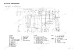
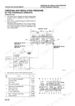
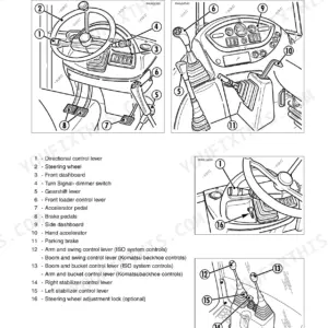
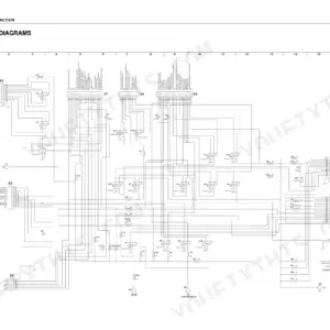
Komatsu printed WEBMPW9500 as the factory shop manual for its PW95-1 hydraulic excavator, and this 440-page Komatsu PW95-1 shop manual PDF is that book, reproduced in full. Hydraulic schematics trace oil from the main pump through the control valve, swing motor relief valve and PPC circuits, while wiring diagrams map harness routing across the electrical system. Testing and Adjusting takes a solid share of the book and walks you through engine speed, valve clearance, compression pressure, steering and travel motor checks; the Maintenance Standard section then sets wear limits for work equipment cylinders, axles and swing machinery. Confirm main pump output at 28 cc/rev maximum displacement, with the check valve rated at 2 bar and the by-pass valve at 3 bar. One wrong relief setting means a second teardown. Once bought, the file is yours: search the text, jump between bookmarked sections, and keep it for as long as the PW95-1 stays in your fleet.
What's Inside This Manual
| System | Pages | Key Topics |
|---|
| Structure and Function | 17-77 | Power Train, Transmission, Front Axle Differential, Rear Axle Differential, Steering System, Main Hydraulic Pump |
| Disassembly and Assembly | 78-92 | Starter Motor, Alternator, Nozzle Holder, Air Filter Group, Muffler, Engine Hood, Fixed Hood |
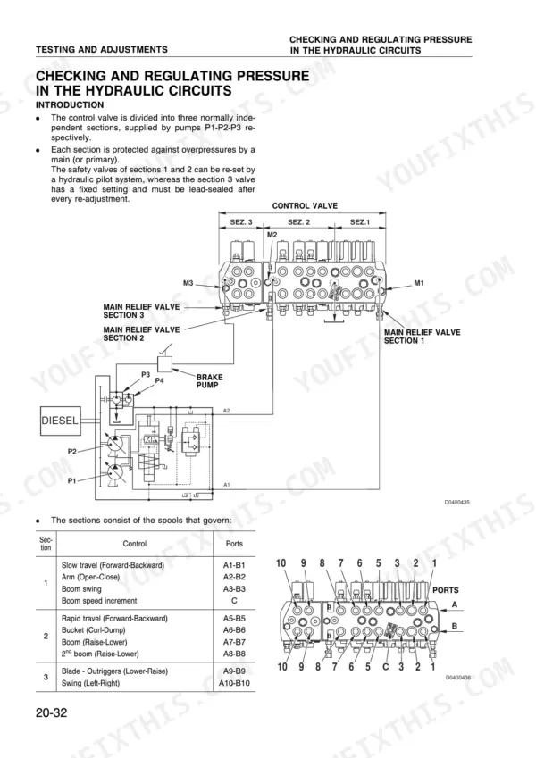
| Testing and Adjusting | 93-111 | Engine Speed, Valve Clearance, Compression Pressure, Hydraulic Circuits, Steering System, Travel Motor |
| Power Train and Axles | 112-119 | P.T.O., Transmission, Differential, Axles, Steering Cylinder |
| Braking and Swing Systems | 120-123 | Parking Brake, Swing Circle, Swing Machinery, Check Valve, Oil Cooler Safety By-Pass |
| Hydraulic System Components | 124-138 | Pump Drive, Summation Horsepower Control, Mode-System, Auxiliary Pump, Control Valve, Swing Motor Relief Valve |
| Travel and Steering Components | 139-144 | Travel Motor, Travel Motor Brake Valves, Servocontrol Feed Unit, Axle Locking Valve, PPC Valves |
| Testing and Adjustments | 145-172 | Checking Wear in the Brake Disks, Adjusting the Parking Brake, Checking the Hydraulic Travel System, Analysis of the Causes of Hydraulic Drifts |
| Troubleshooting | 173-224 | Troubleshooting the Electrical System, Troubleshooting the Hydraulic System |
| Disassembly and Assembly | 225-345 | Starter Motor, Hydraulic Pump, Swing Machinery, Travel Motor, Steering Unit, Axle-Locking Cylinder |
| Complete Front Axle | 346-382 | Complete Rear Axle |
| Work Equipment Cylinders | 383-405 | Removal of Arm, Removal of Boom, Blade and Outriggers |
| Maintenance Standard | 406-440 | Transmission, Steering Cylinder, Swing Circle, Boom Swing PPC Valve, Outrigger and Blade PPC Valves, Axle Locking Cylinder |
Quick Reference Specifications
| Specification | Value | Page |
|---|
| Current rating for 0.35 nominal number wire | 3.5 A | |
| Current rating for 0.5 nominal number wire | 6 A | p. 14 |
| Check valve (4) rated pressure | 2 bar | p. 37 |
| By-pass valve (3) rated pressure | 3 bar | p. 37 |
| Main hydraulic pump max. unitary displacement | 28 cc/rev | p. 39 |
| Main hydraulic pump max. power at 2000 rpm | 44 kW | p. 39 |
| Axle locking valve pilot pressure | 3 bar | p. 70 |
| Steering system cap torque | 50 ± 10 Nm | p. 138 |
| Articulation rotation torque | 15-17 Nm | p. 411 |
| Servocontrol pressure | 35 ± 3.5 bar | p. 96 |
| Safety screws torque | 10 ± 1 kgm (98 ± 9.8 Nm) | p. 386 |
| Flange blocking screws torque | 5 ± 0.5 kgm (49 ± 5 Nm) | p. 387 |