
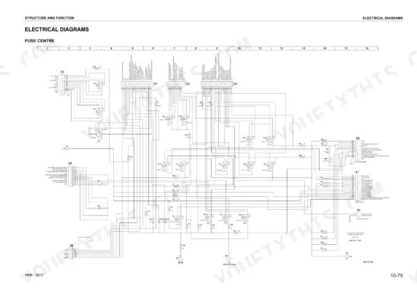
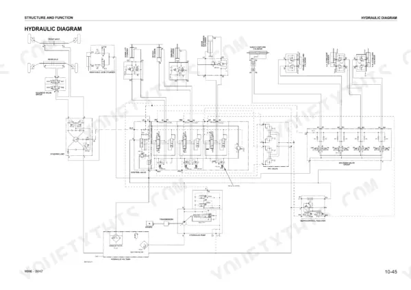
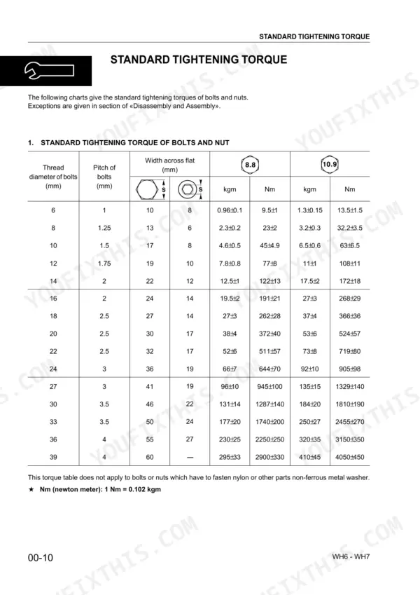
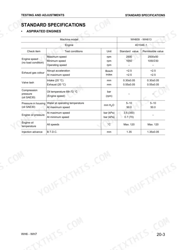
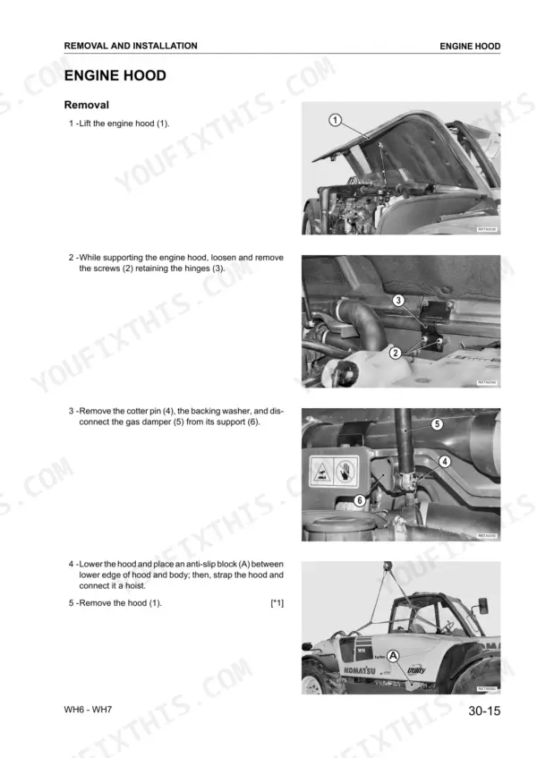
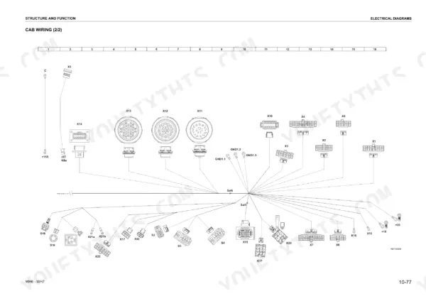
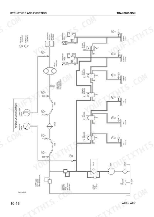

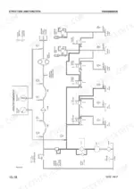
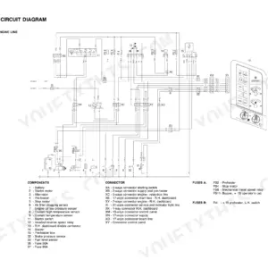
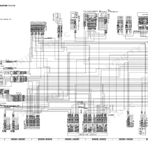
A telehandler whose boom creeps under load, or whose power shift slurs between ranges, rarely gets fixed by guesswork. The Komatsu WH609-1, WH613-1, WH713-1, WH714-1, WH714H-1, WH716-1 shop manual PDF (WEBM005700) runs to 516 pages and covers six telescopic handler variants. Wiring diagrams trace the cab harness and the fuse and relay centre, while hydraulic schematics follow oil from the pump through the safety valves to the lift and offset cylinders. Testing and Adjusting takes up a large share of the book and walks you through engine speed checks and work equipment pressure calibration. Transmission and axle overhaul fills most of the back half. Set the pressure regulator valve between 16.5 and 19.3 bar, and torque M12 8.8 grade bolts to 77 ± 8 Nm. A guessed figure stretches bolts and blows seals. Bookmarks put you on the right chapter in a couple of clicks, and the text layer finds any term you type.
What's Inside This Komatsu WH609-1 to WH716-1 Manual
| System | Pages | Key Topics |
|---|---|---|
| Structure and Function | 27-114 | Transmission, Steering System, Hydraulic Pump, Safety Valves, Cylinders |
| Testing and Adjusting | 115-224 | Standard Specifications, Checking Engine Speed, Checking and Calibrating Work Equipment Hydraulic Pressures, Transmission Power Shift Checks |
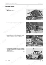
| Engine and Cooling System | 225-269 | Engine Hood, Air Filter, Turbocharger, Exhaust Pipe, Generator, Radiator, Cylinder Head, Injectors |
| Hydraulic and Control Systems | 270-282 | Engine-Transmission Coupling, Control Valve Assembly, Solenoid Valves, Air Conditioner Compressor, Servo-Control Feed Valve |
| Axles and Steering | 283-288 | Front Axle, Rear Axle, Steering Unit, Steering Column |
| Boom and Work Equipment | 289-323 | Telescopic Boom, Lift and Offset Cylinders, Boom Sliding Shoes, Extension and Retraction Chains, Load Cell |
| Cab and Electrical Components | 324-387 | Control Unit, Ballast, Accelerator Cable, Brake Pumps, Wiper Motors, Instrument Panel, Fuse and Relay Centre, Cab |
| Transmission and Axle Overhaul | 388-508 | Transmission Disassembly, Clutch Assembly, Drop Box Assembly, Axle Disassembly, Planetary Reduction, Differential, Bevel Pinion, Steering Cylinder |
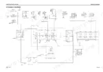
| Other | 509-516 | Cab Wiring, Electrical Diagram |
Quick Reference Specifications
| Specification | Value | Page |
|---|---|---|
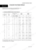
| Standard tightening torque for M6 bolt (8.8 grade) | 9.5 ± 1 Nm | p. 12 |
| Standard tightening torque for M8 bolt (8.8 grade) | 23 ± 2 Nm | p. 12 |
| Tightening torque for 1/2"-20 flared nut | 25.5 ± 4.9 Nm | p. 13 |
| Tightening torque for 9/16"-18 flared nut | 39.2 ± 4.9 Nm | p. 13 |
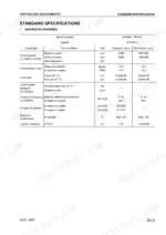
| Pressure regulator valve | 16.5 - 19.3 bar | p. 44 |
| By-pass valve | 2.1 - 3.5 bar | p. 44 |
| Displacement with servocontrol | 250 cc/rev | p. 70 |
| Displacement in emergency | 125 cc/rev | p. 70 |
| Fuse F17 | 3 A | p. 101 |
| Fuse F28 | 7.5 A | p. 101 |
| Engine oil pan capacity (1st filling) | 12.8L | p. 17 |
| Hydraulic system capacity (1st filling) | 117L | p. 17 |
Komatsu WH609-1 to WH716-1 Common Problems This Manual Covers
Komatsu WH609-1 engine minimum or maximum no-load speed reading outside specification on stroboscopic tachometer
Check the accelerator pedal position retainers and the accelerator cable conduit first, as page 156 directs, before touching anything else. Warm the hydraulic oil to 50±5°C, measured with the thermometer sensor on the pump suction pipe, set the transmission in NEUTRAL on firm level ground, and compare maximum no-load speed against 2500±50 rpm. Keep hands clear of hot parts and rotating members while the engine runs (page 156).
Manual Section: Checking engine speed p. 156Engine rpm low during stalled converter test with service brakes applied and 2nd gear engaged
Keep clear of hot parts and rotating members while the engine runs (page 156). Run the engine at maximum speed, hold the service brakes, engage 2nd gear and read rpm once it stabilizes; turbo engines should land between 2015 and 2100 rpm. Hold the stall no longer than 30 seconds and wait at least 15 seconds between tests (page 157). If readings stay out of range, check the engine per manual WHBMNEF000 as page 158 directs.
Manual Section: Checking engine speed p. 157General cut-off valve pressure below calibration when forcing boom down to end of travel
Connect a 600 bar gauge to the control valve pressure tap, with the engine at operating temperature, oil at 50±5°C and parking brakes applied, and force the boom down at IDLE; expect 260±7 bar. If it is off, remove the yellow tamper seal, turn the screw clockwise to raise pressure, torque the retaining nut to 20 Nm, and fit a new orange seal (page 171).
Manual Section: Checking and calibrating work equipment hydraulic pressures p. 169Steering effort high and pressure gauge shows no variation when turning steering wheel
Remove the priority valve plug, spring and stem, noting the assembly sequence, then check the hole and nozzle for cleanliness. Refit the inner plug with Loctite 542 at 20 Nm, keeping Loctite out of the hole (page 173). Remove any excess Loctite from the valve stem, then lubricate the stem, confirm it slides freely, and torque the valve plug to 100 Nm. If steering stays heavy, replace the complete valve stem.
Manual Section: Checking and calibrating work equipment hydraulic pressures p. 173Brake pedal position drops while holding 120 bar during brake pump leak test
Park on firm level ground with stabilizers fully extended or wedges under the wheels. Fit a 250 bar gauge between the pump fitting and feed hose, run at IDLE and pressurize to 120 bar, never exceeding 150 bar (page 179). Inspect both front and rear brakes. Hold for two minutes; if the pedal must move to hold pressure, the pump has internal blow-by, confirmed by stirred oil in the tank.
Manual Section: Brake system checks p. 179Boom lift or boom extension cylinder hydraulic drift with test weight on the forks
Page 211 gives the conditions for all drift inspections: engine at operating temperature, hydraulic oil at 45–55 °C and the test weight on the forks, secured with chains (3500 kg for WH609 and WH613). Each circuit then has its own check conditions: the frame levelling and axle locking cylinders are checked with the boom fully retracted, with no load and the engine not running (pages 217 and 218). Check the cylinders and safety valves for blow-by before you replace anything.
Manual Section: Analysis of the causes responsible for hydraulic drift p. 211Frequently Asked Questions
How do I adjust the air conditioner compressor belt tension?
To tension the belt, loosen the screw (1) and nut (2), then turn the screw (3) clockwise. Apply a 10 kg force at the center of the segment between the compressor and engine pulleys. The resulting deflection 'F' should be 4-6 mm for normal tension or 3 mm for a new belt. p. 159
What is the correct tightening torque for the engine-transmission mounting screws on the Komatsu WH609-1 to WH716-1?
When joining the engine and transmission assemblies, the mounting screws should be tightened to 49 Nm. Make sure the coupling surfaces are clean and dent-free, and tighten them in an alternate and criss-cross manner. p. 271
What is the procedure for bleeding air from the hydraulic cylinders?
Start the engine and run it at high speed for 5 minutes to heat the oil. Return to idle and extend/retract the piston to within 100 mm of the limit stops several times. Stop the engine, top up the oil, then run at maximum speed and repeat the cycle. Finally return the engine to idle and let the piston travel its full stroke until the hydraulic pump is under maximum pressure. p. 165
What is the specified front wheel nut torque on the Komatsu WH609-1, WH613-1, WH713-1, WH714-1, WH714H-1, WH716-1?
The specified tightening torque for the front wheel nuts is 550±11 Nm. p. 285
What is the normal A/C system operating pressure on the Komatsu WH609-1 to WH716-1 at 30°C ambient temperature?
With the engine at 2500 rpm and an ambient temperature of 25/30°C, the normal operating pressure for the A/C system is 15-17 bar. The low pressure side should be 1.6-1.8 bar. p. 99
Is this Komatsu WH609-1 Shop Manual a digital download?
One searchable PDF covering 516 pages, delivered instantly. No disc, no shipping, no waiting on the post.
Is this Komatsu WH609-1 Shop Manual printable?
Yes. Print the pages you need for the job in your own shop, and bin them when they get greasy.



Reviews
There are no reviews yet.