
Within the hour you might be measuring swing ring tilting clearance or pulling the double variable-displacement pump, and this 818-page Liebherr R 914 C, R 924 C service manual PDF is written for that work on both hydraulic excavators. Hydraulic components fill the largest chunk of the book, covering pump installation and dismantling, the fixed-displacement motor and the cylinders, while the hydraulic diagram, adjustment check list and electrical diagram let you trace a circuit and set it to factory values. Swing gear, travel gear brake, track tensioning unit, cab heating and air conditioning, the AHS installation kit and a long central lubrication section round it out. Change the 10 µm hydraulic return filter at 500 operating hours and every 500 after that, and torque the Allen head screws 41 to 87 Nm. Swing ring backlash checks go nowhere without the factory limit. Bookmarks and a live text layer put you on the right section in two clicks.
What's Inside This Liebherr R 914 C, R 924 C Manual
| System | Pages | Key Topics |
|---|---|---|
| General Information | 5-58 | Safety Instructions, Tightening Torques, General Instructions for Lubricants |
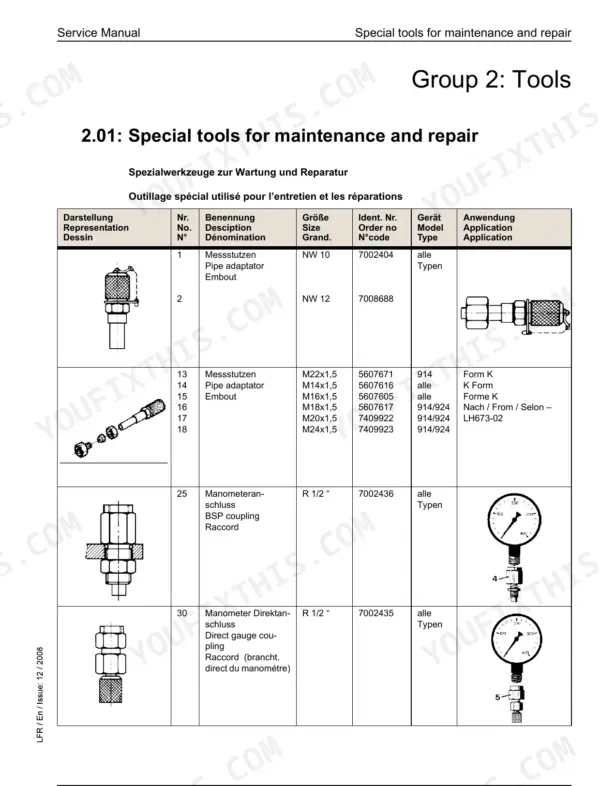
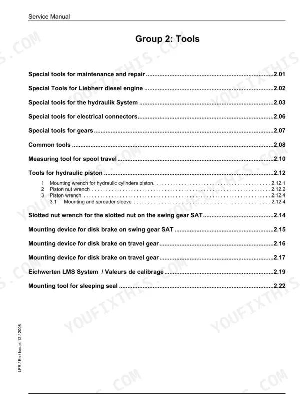
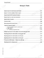
| Tools | 59-118 | Special Tools for Maintenance, Special Tools for Diesel Engine, Special Tools for Hydraulic System |
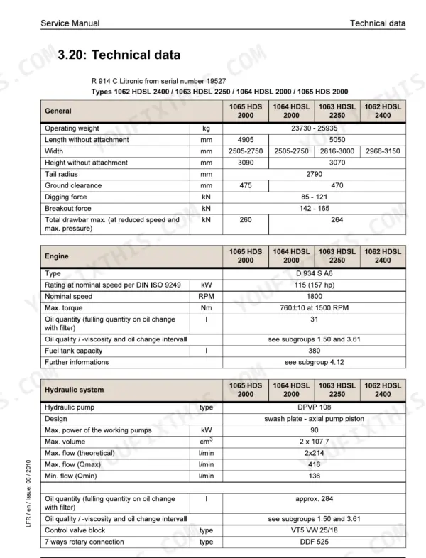
| Technical Data / Maintenance Guidelines | 119-144 | Technical Data, Inspection and Maintenance Schedule, Lubrication Chart |
| Engine | 145-150 | Technical Data for Engine |
| Coupling / Splitterbox | 151-158 | Coupling, Splitterbox |
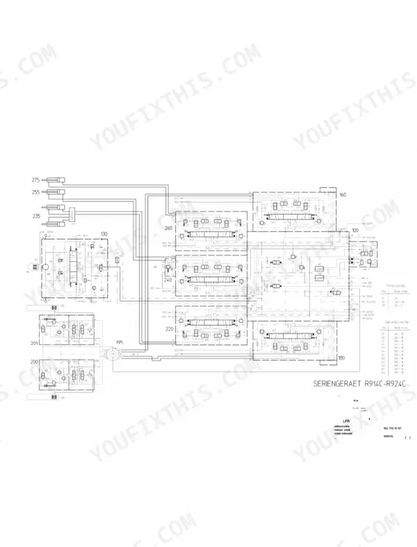
| Hydraulic System | 159-186 | Adjustment Check List, Hydraulic Diagram |
| Hydraulic Components | 187-326 | Installation and Dismantling of Pumps, Double Variable-Displacement Pump, Hydraulic Fixed-Displacement Motor, Hydraulic Cylinders |
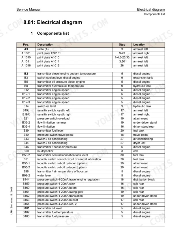
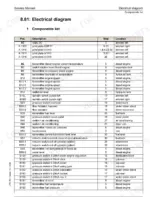
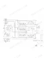
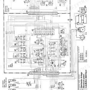
| Electrical System | 327-371 | Arrangement of Components, Electrical Diagram |
| Swing Gear | 372-373 | Swing Gear Transmission, Swing Brake, Hydraulic Motor, Secondary Pressure Relief Valve, Slotted Nut, Mounting Device |
| Swing Ring | 374-383 | Ball Track Lubrication, Swing Ring Teeth, Tilting Clearance, Circumferential Backlash, Outer Ring, Internal Ring |
| Travel Gear | 384-395 | Travel Gear Brake, Slide Ring Seal |
| Track Components | 396-431 | Wear of Travel Gear Parts, Dismantling and Installing Travel Gear, Tensioning Unit |
| Options | 432-590 | Hydraulic Installation Kit AHS, Schematics Chart for Options |
| Cab / Heater / Air Conditioning System | 591-648 | Auxiliary Heating, Heating and Air-Conditioning System |
| Central Lubrication | 649-818 | Centralized Lubrication System, Pump of Centralized Lubrication, Progressive Distributor |
Quick Reference Specifications
| Specification | Value | Page |
|---|---|---|
| R 914 C / R 924 C with DPVP 108 pump (from serial 23079 / 23085) | ||
| Allen head screws 41 torque | 87 Nm | p. 200 |
| Screw plug 1 / 9 torque | 35 Nm | p. 204 |
| Sealing nut 7 torque | 18 Nm | p. 204 |
| Flow regulator 24.5 installation torque | 5 Nm max. | p. 205 |
| All Models | ||
| Hydraulic oil return filter (20 / 5 µm) replacement interval | first change after 500 operating hours, then every 1000 operating hours | p. 51 |
| Hydraulic oil return filter (10 µm) replacement interval | first change after 500 operating hours, then every 500 operating hours | p. 51 |
| R 924 Compact | ||
| Cylinder head screws 6 torque | 68 Nm | p. 191 |
| Hexagon head screws 12 torque | 68 Nm | p. 191 |
| R 914 C / R 924 C with hydraulic installation kit AHS 12 | ||
| Stroke limitation of control piston 503 Dimension Y of stop screw 500.1 | 8.5 mm | p. 437 |
| Stroke limitation of control piston 503 Dimension Y of stop screw 500.2 | 8.5 mm | p. 437 |
| R 914 C / R 924 C with AHS 11 with Tool Control | ||
| Pressure cut-off 101 | 350 +10 bar | p. 448 |
| Secondary pressure relief valve 501 (Extend cylinder 511, EV6 at 0%) | 100 ±10 bar | p. 449 |
Liebherr R 914 C, R 924 C Common Problems This Manual Covers
Liebherr R 914 C / R 924 C servo pressure, horsepower regulation or swing motor pressure out of adjustment
Check servo pressure first, then work through horsepower regulation, hydraulic regulation and swing motor pressure using the Adjustment Check List for your exact machine. The R 914 C and R 924 C have separate lists in the Hydraulic System section starting page 159. Record every reading before touching an adjuster so a bad change can be undone.
Manual Section: Hydraulic System p. 159Hydraulic pump leaking or not bled of trapped air after reinstallation and first start-up
Bleed the pump before the first start, following the start-up and bleeding procedure in the Hydraulic Components section. Then run it and inspect every joint for leaks. When refitting gear pump 30, torque the Allen head screws 41 to 87 Nm as page 200 specifies; the book warns that ignoring that figure risks damaging the pump.
Manual Section: Hydraulic Components p. 187Hydraulic installation kit AHS 11 hammer circuit pressure off setting at secondary pressure relief valves 501 and 502, which control cylinder extension and hammer operation
Check pressure cut-off 101 first against 350 +10 bar on page 448. Then set secondary pressure relief valves 501 and 502 to the values on page 449 for the stage and EV6 setting you are testing. Measure return flow dynamic pressure as well; it must not exceed 2 bar. Verify control piston stroke limitation (dimension Y) at 8.5 mm.
Manual Section: Options p. 449Air conditioning showing an error code, weak cooling effect or noisy compressor
Check which error code the system shows, then work through the Air-Conditioning System Faults list for start-up, cooling effect and compressor noise complaints. If cooling is weak, verify the refrigerant charge against approx. 1.6 kg as given on page 615. A whistling V-belt is on the same fault list, so inspect it before you condemn the compressor.
Manual Section: Cab / Heater / Air Conditioning System p. 615Auxiliary heating unit showing a fault code with a suspected flame scanner fault
Check the fault code against the error descriptions in the Auxiliary Heating Troubleshooting pages of the Cab / Heater / Air Conditioning System section, then carry out the remedial measure listed for that code. Test the flame scanner using the check procedure given there before you order parts or pull the heater.
Manual Section: Cab / Heater / Air Conditioning System p. 591Centralized lubrication system leaking, pump not delivering, blocked circuits or proximity sensor fault
Match the symptom in the Research of breakdowns and propositions of solutions table on page 659. Grease leaking at the relief valve points to excessive system pressure or a blocked progressive distributor. If the pump is out of order, check the electric supply to the motor before replacing the pump. If no grease reaches any lubrication point, check the proximity sensor connections and the number of impulses and cycle time.
Manual Section: Central Lubrication p. 649Frequently Asked Questions
How do I reset auxiliary heater fault codes on a Liebherr R 914 C or R 924 C?
To release the locking and delete fault codes, first remedy the cause of the error. Then, press buttons 65 and 66 simultaneously for at least 2 seconds. The control unit will be unlocked and the stored errors F1 to F5 will be deleted. p. 606
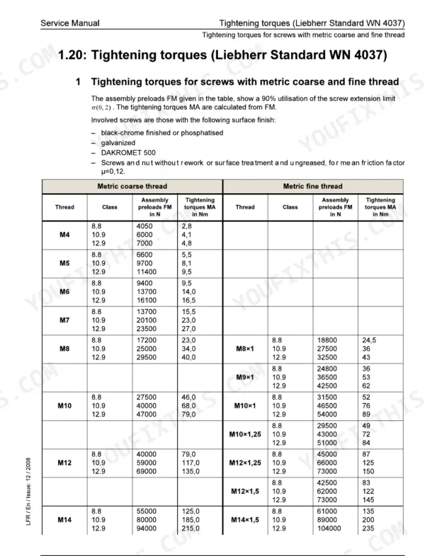
What are the torque specifications for screws with metric coarse and fine threads for the R 914 C and R 924 C?
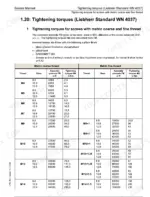
Tightening torques depend on the thread size and class. For example, an M10 screw of class 8.8 requires 46 Nm, class 10.9 requires 68 Nm, and class 12.9 requires 79 Nm. Detailed tables for all sizes are provided in the manual. p. 23
What is the oil change interval for the diesel engine on the R 914 C and R 924 C?
The oil change interval depends on the operating conditions and fuel sulphur content. For temperatures normally not dropping below -10°C with fuel sulphur content max 0.5%, the interval is 250 hours for CF-4/CG-4/CH-4/CI-4 oil quality and 500 hours for E3/E4 oil quality. p. 48
What is the correct procedure for bleeding the hydraulic pumps after replacement?
After replacing the pump, fill the hydraulic tank to the upper mark and open the shut-off valve. Loosen the leak oil line T1 on the pump until oil without foam flows out, then tighten it. Run the system at full load until the oil reaches at least 50°C and check for leaks. p. 193
What is the tightening torque for the gear pump 30 Allen head screws on the Liebherr R 914 C / R 924 C?
When installing the gear pump 30, the Allen head screws 41 must be tightened to a torque of 87 Nm to prevent damage to the pump. p. 200
What exactly do I receive with this Liebherr R 914 C Service Manual?
Straight to your device: 818 pages of searchable Service Manual, downloadable the moment payment goes through.
Can I print this Liebherr R 914 C manual?
You can. Print the sections you want for your own use and keep the file as your backup.


Reviews
There are no reviews yet.