
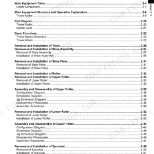
This is the factory shop manual for Link-Belt Quantum series 2650Q and 2700Q hydraulic excavators, book number WEL2710-0E, delivered as a 782 page PDF download. Both machines are covered side by side, from lower and upper mechanism specifications through complete disassembly and servicing procedures.
When a final drive is apart on the floor and the crew is standing still waiting on one bolt torque or a relief pressure figure, this is the book that carries it. Inside are maintenance standards, tightening torques for major parts, and step by step teardown and rebuild procedures for the hydraulic pump, travel and swing mechanisms, control valve, cylinders, and remote control valve.
Keep it on the laptop in the service truck or print the section you need for the bench, work through the procedure, and get the machine digging again.
What's Inside This Link-Belt 2650Q, 2700Q Manual
| System | Pages | Key Topics |
|---|---|---|
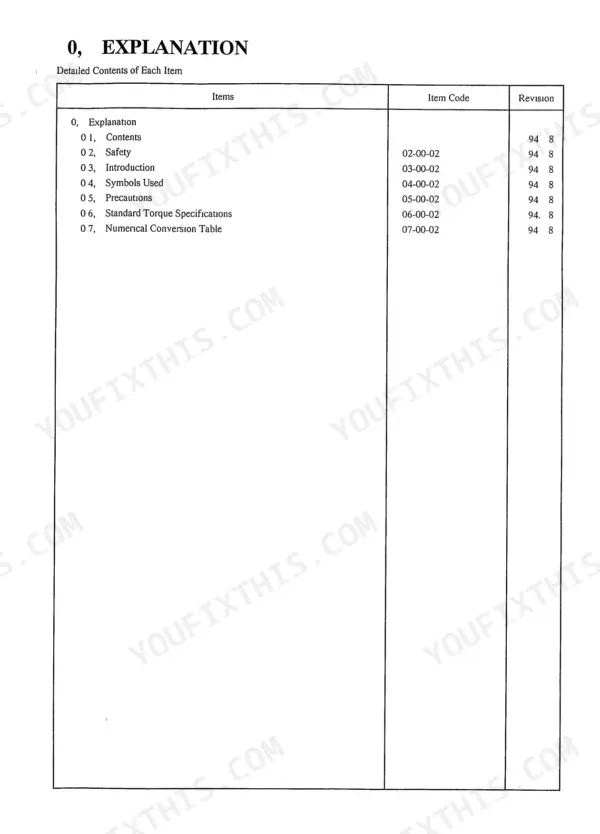
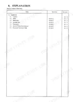
| Shop Manual Explanation | 3-46 | Contents, Safety, Introduction, Symbols Used, Precautions, Standard Torque Specifications, Numerical Value Conversion Table |
| General | 47-78 | Lower Mechanism Specifications, Upper Mechanism Specifications, Engine Specifications, Hydraulic Equipment Specifications |
| Performance | 79-84 | Main Body Weight |
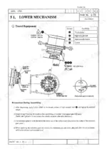
| Main Body Disassembly and Servicing Procedures | 85-174 | Lower Mechanism, Upper Mechanism, Attachment Disassembly, Maintenance Standards |
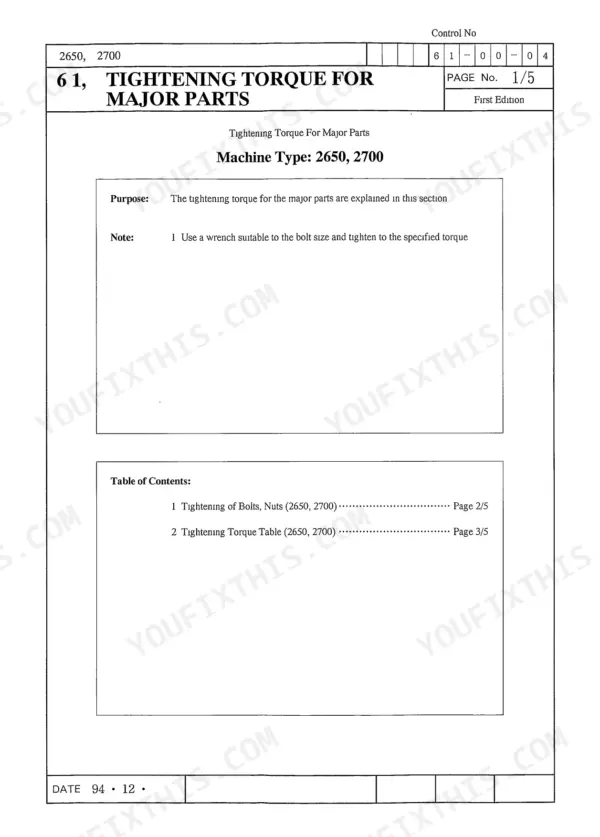
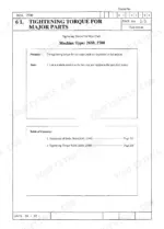
| Major Components Disassembly and Servicing Procedures | 175-232 | Tightening Torque for Major Parts, Take-Up Roller, Upper Roller, Lower Roller, Recoil Spring, Rotating Joint Disassembly |
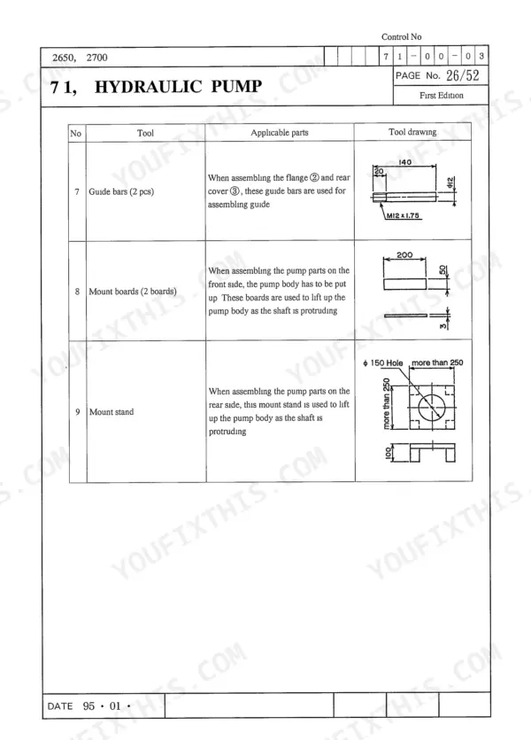
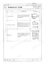
| Hydraulic Pump | 234-350 | Pump Disassembly and Maintenance |
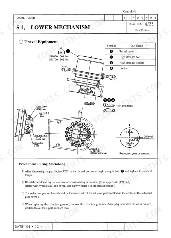
| Travel Mechanism | 351-476 | Operating Principle and Precautions, Maintenance Procedures |
| Swing Mechanism | 477-548 | Motor Assembly, Motor Subassembly, Reduction Gear Subassembly |
| Control Valve | 549-642 | Control Valve Servicing |
| Cylinder | 643-696 | Specifications and Structure, Operation Principle, Servicing Procedures |
| Remote Control Valve | 697-758 | Operation, Travel |
| Valves | 759-780 | 8-Spool Solenoid Valve, Shuttle Valve, Cushion Valve, Stacked Valve |
Quick Reference Specifications
| Specification | Value | Page |
|---|---|---|
| Hexagonal head bolt M6 torque | 6.9 Nm | p. 34 |
| Fuel tank mounting bolts torque | 166.3-213.3 ft-lbs | p. 59 |
| Main relief set pressure (Standard) | 4550 psi | p. 66 |
| Main relief set pressure (Boost) | 4977 psi | p. 66 |
| Hydraulic oil contamination measurement interval (Duty cycle 10%) | Every 800 hrs | p. 76 |
| Hydraulic oil contamination measurement interval (Duty cycle 20%) | Every 600 hrs | p. 76 |
| Control valve (2700) mounting bolt torque | 196-230 ft-lb | p. 127 |
| Remote control valve tightening torque | 35-42 N-m | p. 129 |
| Rod total length (S1~S7) | 6mm | p. 732 |
| Body inner diameter (S8) | 12mm | p. 732 |
| Hex socket head cap screw torque | 3.4-4.4 Nm (35-45 kgf cm) | p. 757 |
| 2650 Lower Total Weight | 9020 lbs | p. 47 |
Link-Belt 2650Q, 2700Q Common Problems This Manual Covers
Weak digging force or sluggish hydraulics
When the machine slows down and will not pull a full bucket, the usual suspects are relief valve settings, a tired pump, or a sticking control valve spool. The manual specifies main relief pressure at 4550 psi standard and 4977 psi on boost, then walks through hydraulic pump and control valve disassembly.
Manual Section: Major Hydraulic Component Disassembly and Servicing Procedures p. 233Loose track or thrown track chain
A track that keeps coming off usually traces back to a weak recoil spring or a failing take-up roller. The manual has separate recoil spring procedures for the 2650 and 2700, plus take-up, upper, and lower roller disassembly with tightening torques for each.
Manual Section: Major Components Disassembly and Servicing Procedures p. 175Machine pulls to one side traveling
One track lagging the other points at a travel motor or travel mechanism problem on that side. The travel mechanism disassembly procedure lets you open the unit, inspect it, and rebuild it to spec instead of guessing at a swap.
Manual Section: Major Hydraulic Component Disassembly and Servicing Procedures p. 233Boom or arm cylinder drift
A boom that settles under load or an arm that creeps means bypassing cylinder seals or a leaking overload relief. The cylinder disassembly procedures cover teardown, seal replacement, and reassembly for the hydraulic cylinders on both machines.
Manual Section: Major Hydraulic Component Disassembly and Servicing Procedures p. 233Oil leaking at the rotating joint
Hydraulic oil showing up between the upper structure and the undercarriage often comes from worn seals in the rotating joint that feeds the travel circuit. The rotating joint disassembly procedure shows how to pull it apart and reseal it.
Manual Section: Major Components Disassembly and Servicing Procedures p. 175Worn bucket pins and bushings
Slop at the bucket and arm connections wears fast once it starts and ruins digging accuracy. The attachment disassembly procedures and maintenance standards give you the teardown sequence and the wear limits that tell you when pins and bushings are done.
Manual Section: Main Body Disassembly and Servicing Procedures p. 85Contaminated hydraulic oil killing components
Dirty oil quietly eats pumps, motors, and valves long before anything obviously fails. The manual sets contamination measurement intervals by duty cycle, from every 800 hours at 10 percent duty down to every 200 hours at 100 percent.
Manual Section: General p. 47Frequently Asked Questions
Which Link-Belt excavators does this shop manual cover?
It covers the Link-Belt Quantum series 2650Q and 2700Q hydraulic excavators. This is factory book number WEL2710-0E, and specifications, procedures, and torque tables inside are given for both the 2650 and 2700 wherever they differ. p. 1
Does it include hydraulic pressure specifications?
Yes. The General section lists hydraulic equipment specifications, including main relief set pressure at 4550 psi standard and 4977 psi on boost, plus overload relief settings such as 5190 psi for boom raise, arm, and bucket circuits. p. 47
Are undercarriage torque specs included?
Yes. The tightening torque table for major parts covers the travel motor, drive sprocket, take-up roller, upper and lower rollers, track guard, and shoe bolts. Travel motor and roller bolts, for example, are listed at 200 to 230 ft-lbs. p. 179
Does the manual cover the engine?
The General section includes engine specifications for the Isuzu 4BD1 diesel used in these machines, listing the 2650 at a rated 88 PS. For full engine overhaul detail, this shop manual focuses on the machine itself: hydraulics, undercarriage, swing, and structures. p. 47
Is this Link-Belt 2650Q manual a download or a disc?
Immediate download of the complete 782-page searchable Shop Manual. Access it on any device, from a laptop at your desk to a phone in the field.
Are there any print restrictions on this Link-Belt 2650Q manual?
Yes. The PDF has no DRM restrictions, so print any page or section you need for your shop. Works with any standard printer.



Reviews
There are no reviews yet.