
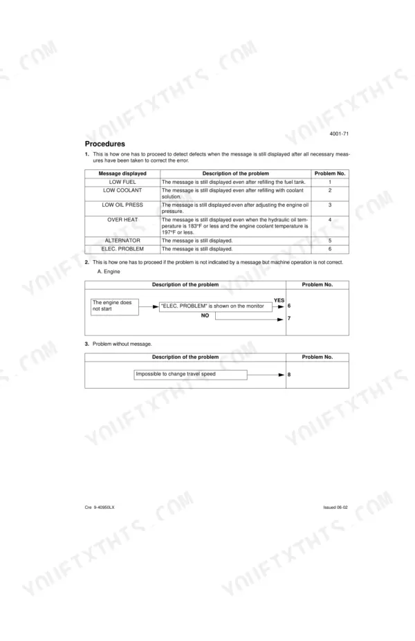
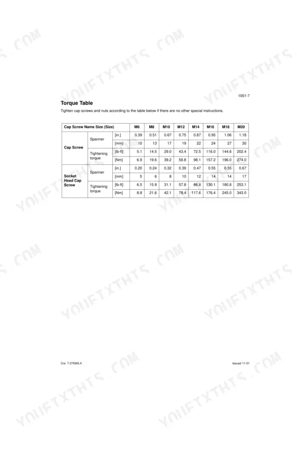
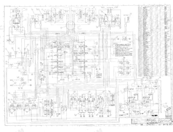


This 606-page Link-Belt 330LX Service Manual PDF (OEM #1060) walks you through the complete crawler excavator: Kawasaki and Uchida pump teardowns, travel motors, swing reduction gear, and the full electrical system. You get hydraulic circuit diagrams for every function (boom, dipper, bucket, swing, crusher and breaker circuits), machine wiring diagrams, and an electrical troubleshooting section that runs from monitor displays down to individual sensor inspection. Inside: standard and special torque data, track tension adjustment, pressure setting procedures, and step-by-step disassembly for the main control valve and pilot function blocks. Follow the factory rules exactly: replace every O-ring and backup ring during reassembly, and never dry bearings with compressed air. No more chasing wiring faults with a multimeter and a prayer. Bookmarked PDF; search any spec by keyword, walk out to the machine, and start wrenching.
What's Inside This Link-Belt 330LX Manual
| System | Pages | Key Topics |
|---|---|---|
| General Information | 5-12 | Safety, Standard Torque Data, Cleaning, Inspection |
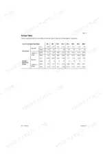
| Specifications and Special Torque Settings | 13-36 | Machine Serial Numbers, Fluid Specifications, Engine Oil Viscosity, Track Assembly Dimensions, Attachment Linkage Wear Limits |
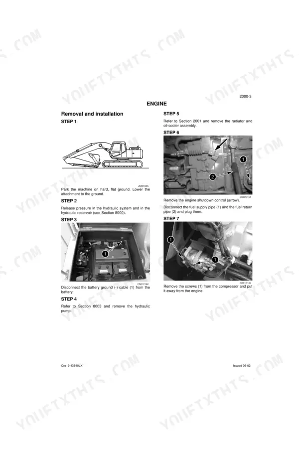
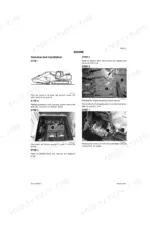
| Engine | 37-42 | Engine Removal, Engine Installation, Radiator Removal, Oil-Cooler Removal |
| Radiator and Oil-Cooler | 43-48 | Radiator Removal, Oil-Cooler Removal, Installation, Cooling System Capacity |
| Fuel System | 49-54 | Fuel Tank Removal, Fuel Tank Installation, Fuel Sensor, Fuel Filter |
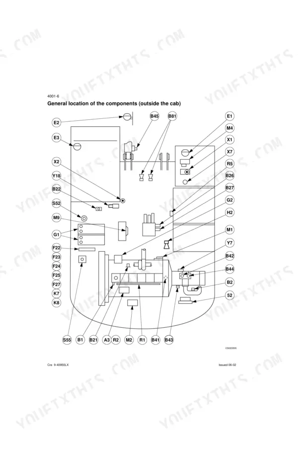
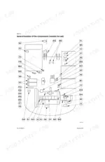
| Electrical System | 55-146 | Electrical Troubleshooting, Monitor Displays, Fuse Box, Component Location, Sensor Inspection |
| Batteries | 147-156 | Safety Instructions, Electrolyte Level, Battery Charging, Booster Battery Connection |
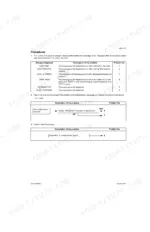
| Main Electronic Control Box | 157-160 | Control Box Removal, Control Box Installation, Engine Electronic Control Box |
| Undercarriage | 161-214 | Track Removal, Track Installation, Track Tension Adjustment, Roller Disassembly, Idler Wheel Assembly |
| Drive Train | 215-252 | Travel Motor Removal, Swing Reduction Gear Disassembly, Travel Reduction Gear Assembly |
| Hydraulic System General Procedures | 253-296 | Pressure Release, Bleeding Air, Vacuum Pump, Hydraulic System Cleaning, Specifications, Troubleshooting, Pressure Setting, Component Identification |
| Hydraulic Reservoirs & Pumps | 297-394 | Hydraulic Reservoir Removal, Hydraulic Reservoir Installation, Main Hydraulic Pump, Pilot Pump, Pump Coupling, Kawasaki Pump Disassembly, Uchida Pump Disassembly, Pump Assembly |
| Control Valves & Levers | 395-484 | Main Control Valve, Pilot Function Blocks, Control Levers, Travel Pedal Control, Solenoid Valves, Cushion Control Valve, Safety Valves, Disassembly |
| Hydraulic Functions & Travel Motor | 509-554 | Hydraulic Circuit Diagrams, Travel Modes, Swing Circuit, boom/dipper/bucket Circuits, crusher/breaker Circuits, Travel Motor assembly/disassembly, Brake Valve |
| Upperstructure | 555-604 | Turntable Inspection, Counterweight Removal, Boom Removal, Dipper Installation, Bucket Shimming |
Quick Reference Specifications
| Specification | Value | Page |
|---|---|---|
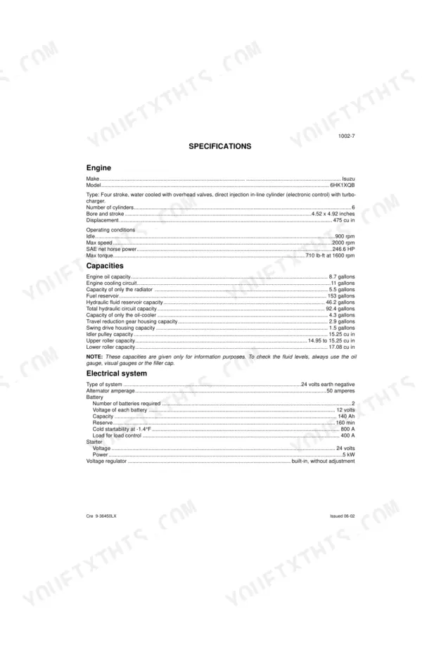
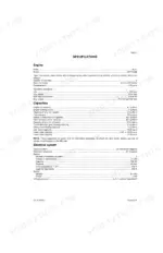
| Engine Model | 6HK1XQB | p. 19 |
| Engine Displacement | 475 cu in | p. 19 |
| Engine Max Speed | 2000 rpm | p. 19 |
| Engine Oil Capacity | 8.7 gallons | p. 19 |
| Fuel Reservoir Capacity | 153 gallons | p. 19 |
| Hydraulic Fluid Reservoir Capacity | 46.2 gallons | p. 19 |
Link-Belt 330LX Common Problems This Manual Covers
Link-Belt 330LX shows trouble code 488, intake air temperature readings jump around, engine runs rough
Check the error code reference to confirm code 488 points at the intake air temperature sender. Unplug the sender connector and inspect the pins for corrosion, then trace the circuit against the wiring diagram. Verify the 24 volt supply is stable at the sender before condemning it; replace the sender if readings still drift.
Manual Section: Electrical System, Electrical and Electronic TroubleshootingMonitor flashes M0080 after long digging cycles, power lift and auto idle stop responding
Check code M0080 against the error code reference; it often sets after prolonged use of a single function and is non-critical if the system worked before. Cycle the key switch and retest both functions. If the code returns, follow the troubleshooting procedures and verify the 24 volt supply holds steady at the control box.
Manual Section: Electrical System, Electrical and Electronic TroubleshootingBoom length sensor won't calibrate, monitor throws intermittent CAN bus communication faults
Inspect the boom length reel connector first; a loose plug on the CAN bus mimics a dead control module. Check harness routing against the wiring diagram for chafe points at the boom foot. Measure supply voltage at the sensor; anything sagging below the 24 volt system spec means wiring resistance. Test the control module last, using the removal steps on page 157.
Manual Section: Main Electronic Control Box p. 157Engine cranks slowly in cold weather, sometimes won't turn over at all
Check electrolyte level and state of charge in both 12 volt batteries using the procedures starting on page 147. Never charge a battery with frozen electrolyte; thaw it first, per the warning on page 149. Load test each battery, then clean and tighten the ground connections. If cranking speed recovers, inspect the alternator charge circuit before the next cold snap.
Manual Section: Batteries p. 147Machine pulls to one side when traveling straight, one track noticeably slower
Measure delivery pressure at P1 and P2 with the track raised; a pressure difference between sides points to the pump or travel motor on the slow side. Verify each pump section still makes its rated 75 gpm flow, listed on page 20. Check the travel motor for internal leakage, and replace the needle and tapered roller bearings if damaged or past 3000 hours, per page 501.
Manual Section: Travel Drift TroubleshootingFrequently Asked Questions
How to reset Link-Belt 330LX error codes?
To erase failure codes and the number of hours from the diagnostic screens DIAG2 and DIAG3, press the work mode switch for a minimum of 10 seconds. This action records the data in the electronic control box memory. p. 111
What are the torque specs for Link-Belt 330LX engine bolts?
The retaining screws for the engine should be tightened to a torque of 231 ± 18 lb-ft. This specification is found in the torque setting section for the engine. p. 38
What does error code m0080 indicate on Link-Belt 330LX?
Error code M0080 indicates a problem with the 'Upper or travel pilot pressure switch'. This code is listed under the excavator failure detection diagnostic screen DIAG4. p. 111
What is the engine oil capacity for the Link-Belt 330LX?
The engine oil capacity for the Link-Belt 330LX is 8.7 gallons. This is a key specification listed under the machine's general capacities. p. 19
What is the standard main circuit relief pressure setting for the Link-Belt 330LX hydraulic system?
The standard main circuit relief pressure setting for the Link-Belt 330LX hydraulic system is 4975 ± 43 psi. This value is critical for the proper functioning of the hydraulic circuits. p. 20
Is this Link-Belt 330LX Service Manual a digital download?
This is a 606-page searchable PDF ready for immediate download. Works on any device, so pull it up on your phone while you're under the hood. No shipping, no waiting.
Can I print this Link-Belt 330LX manual?
Yes. The PDF has no DRM restrictions, so print any page or section you need for your shop. Works with any standard printer.


Reviews
There are no reviews yet.