
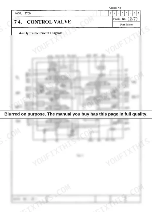
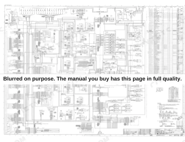
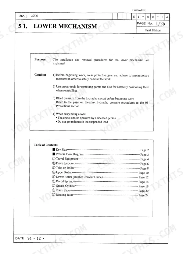
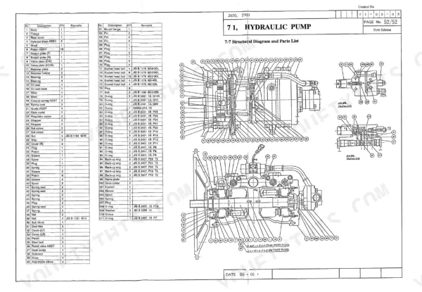
The Link-Belt 2650Q, 2700Q shop manual PDF, book number WEL2710-0E, strips both Quantum series excavators down to the swing bearing across 782 pages of factory disassembly and servicing procedures. Hydraulic schematics map the control valve circuits, load holding valve, arm regeneration and travel priority included, and a wiring diagram closes out the book. Maintenance standards give you wear limits for rollers, idlers and the recoil spring, so you can measure a track component and call it serviceable or scrap on the spot. Torque the travel motor mounting bolts to 200-230 ft lbs, then set the pump relief valve assembly at 61 ft lbs, straight from the factory tables. Guesswork here costs a second teardown. This bookmarked, text-searchable PDF rides along on whatever screen is closest to the machine.
What's Inside This Link-Belt 2650Q, 2700Q Manual
| System | Pages | Key Topics |
|---|---|---|
| Shop Manual Explanation | 3-46 | Contents, Safety, Introduction, Symbols Used, Precautions, Standard Torque Specifications, Numerical Value Conversion Table |
| General | 47-78 | Lower Mechanism Specifications, Upper Mechanism Specifications, Engine Specifications, Hydraulic Equipment Specifications |
| Performance | 79-84 | Main Body Weight |
| Main Body Disassembly and Servicing Procedures | 85-174 | Lower Mechanism Disassembly, Upper Mechanism Disassembly, Attachment Disassembly, Maintenance Standards |
| Major Components Disassembly and Servicing Procedures | 175-232 | Tightening Torque for Major Parts, Take-Up Roller Disassembly, Upper Roller Disassembly, Lower Roller Disassembly, Recoil Spring Disassembly, Rotating Joint Disassembly |
| Hydraulic Pump Disassembly and Maintenance | 233-294 | Hydraulic Pump, Piston Pump, Gear Pump, Regulator, Relief Valve, Solenoid Proportional Control Valve |
| Travel Mechanism (2650/2700) | 295-350 | Travel Mechanism, Hydraulic Motor, Brake Valve, Parking Brake, 2-Speed Switch Mechanism |
| Travel Mechanism Disassembly and Maintenance | 351-412 | Travel Mechanism Disassembly, Reduction Gear, Hydraulic Motor Parts, Brake Valve Parts, Assembly Procedures |
| Cylinder Specifications and Structure | 413-476 | Cylinder Specifications, Boom Cylinder, Arm Cylinder, Bucket Cylinder, Cylinder Maintenance Standards |
| Swing Mechanism | 477-548 | Swing Motor Assembly, Reduction Gear, Mechanical Brake, Make-Up Valve, By-Pass Valve |
| Control Valve | 549-730 | Control Valve Actuation, Load Holding Valve, Logic Check Valve, Arm Regeneration Circuit, Travel Priority Circuit |
| Solenoid Valve (8-Spool) | 731-782 | 8-Spool Solenoid Valve, Hydraulic Circuit, Solenoid Valve Structure, Valve Disassembly, Valve Reassembly |
Quick Reference Specifications
| Specification | Value | Page |
|---|---|---|
| 2650 | ||
| Boom cylinder mounting bolt tightening torque, 2650 | 29.4 ± 5.5 ft lbs (4.06 ± 0.76 kgf-m) | p. 647 |
| 2700 | ||
| Boom cylinder mounting bolt tightening torque, 2700 | 23.2 ± 4.3 ft lbs (3.21 ± 0.60 kgf-m) | p. 659 |
| All Models | ||
| Hydraulic pump mounting bolt tightening torque | 24 ft lbs (3.3 kgf-m) | p. 283 |
| Hydraulic pump relief valve assembly tightening torque | 61 ft lbs (8.5 kgf-m) | p. 283 |
| Travel motor mounting bolt tightening torque | 200-230 ft lbs (266.6-311.6 Nm) | p. 179 |
| Drive sprocket mounting bolt tightening torque | 200-230 ft lbs (266.6-311.6 Nm) | p. 179 |
| Travel motor oil seal tightening torque | 203 ft lbs (28.0 kgf-m) | p. 284 |
| Throttle motor mounting bolt tightening torque | 9.4 ft lbs (1.3 kgf-m) | p. 60 |
| Pilot signal pressure for travel mechanism | 569 psi (40 kgf/cm²) | p. 315 |
| Solenoid Valve Rated Voltage | 20-32 Volt | p. 736 |
| 2650Q | ||
| 2650 Lower Total Weight | 9020 lbs | p. 47 |
| 2650 Rated Horsepower | 88 Ps | p. 57 |
Link-Belt 2650Q, 2700Q Common Problems This Manual Covers
Link-Belt 2650Q controls randomly stay locked after startup, joysticks dead for several minutes
Check supply voltage at the 8-spool solenoid valve first; the coils are rated 20 to 32 volts, spec on page 736. If voltage drops out intermittently, trace the harness against the wiring diagram and clean every ground and connector in the pilot control circuit before condemning the valve.
Manual Section: Solenoid Valve (8-Spool) p. 736Loud rattle or knock between engine and hydraulic pump, then sudden loss of all functions
Remove the pump and inspect the drive coupling for chewed splines and rubber debris; the disassembly procedure starts on page 233. Replace the coupling as an assembly, check the pump input shaft splines for wear, then remount the pump and torque the mounting bolts to 24 ft lbs (3.3 kgf-m), spec on page 283.
Manual Section: Hydraulic Pump Disassembly and Maintenance p. 283Machine pulls hard to one side during travel, one track slow or noisy
Check pilot signal pressure at the slow side; the travel circuit should show 569 psi (40 kgf/cm2), spec on page 315. Swap pilot lines side to side to isolate the control valve from the travel motor. If the motor comes off, reinstall it with mounting bolts torqued to 200 to 230 ft lbs per page 179.
Manual Section: Travel Mechanism (2650/2700) p. 315Hydraulic oil runs hot and digging power fades after the first hour of work
Drain a sample, check oil level and condition, then replace the hydraulic filters and clean the cooler fins. Test pump delivery using the pump maintenance section starting on page 233; low flow with abnormal noise means internal wear. During reseal, torque the relief valve assembly to 61 ft lbs (8.5 kgf-m), spec on page 283.
Manual Section: Hydraulic Pump Disassembly and Maintenance p. 233Track chain jumps and clatters over worn sprocket teeth, undercarriage noisy on rough ground
Measure sprocket tooth and track chain wear against the maintenance standards in the major components section starting on page 175. Replace worn sprockets, rollers, and idlers in matched sets, then torque drive sprocket mounting bolts to 200 to 230 ft lbs (266.6 to 311.6 Nm), spec on page 179. Reset track tension afterward.
Manual Section: Major Components Disassembly and Servicing Procedures p. 179Frequently Asked Questions
What are the torque specifications for the major bolts on the Link-Belt 2650Q and 2700Q?
The torque specifications for major bolts are provided in the Standard Torque Specifications table. For example, an M10 hexagonal head bolt requires 23.9 ft lbs (32.3 N m) of torque, while an M20 hexagonal head bolt requires 202.6 ft lbs (274.0 N m). p. 34
What are the replacement specifications for the hydraulic pump on the Link-Belt 2650Q and 2700Q?
The hydraulic pump for the 2650Q has a maximum output of 32.4 gpm (122.7 l/min) at 2230 rpm, while the 2700Q pump has a maximum output of 36.9 gpm (139.8 l/min) at 2230 rpm. Both models use a twin variable displacement piston pump with a working pressure of 4550 psi (320 kgf/cm²). p. 61
What is the replacement interval for the engine oil filter on the Link-Belt 2650Q and 2700Q?
The engine oil filter element (both full flow and by-pass) should be replaced every 500 hours of operation. p. 73
What is the tightening torque for the reamer bolt on the 2650/2700 travel mechanism?
The reamer bolt [19] on the travel mechanism requires a tightening torque of 398 ± 51 ft lbs (55 ± 7 kgf-m). p. 390
What is the procedure for bleeding air from the travel motor after assembly?
After assembling the travel motor, bleed the air by filling the motor with hydraulic oil. Loosen the plug (PF1/2) at the air bleeder port to let oil into the port, then run the motor at low speed to bleed air from the lines. p. 91
Is this Link-Belt 2650Q manual a download or a disc?
A single searchable PDF file of 782 pages, downloadable right after payment. Nothing ships, nothing waits in the mail.
Am I able to print pages from this Link-Belt 2650Q manual?
Yes. It prints from any PDF reader, so run off the pages you need for your own repair work.



Reviews
There are no reviews yet.