
This is the Manitou service manual for the Z55 and 550Z compact excavators (form number 50940331), the same machine sold across the Gehl and Mustang lines and powered by the 4TNV86CT-PBV diesel. Its 760 pages cover the full machine: engine, fuel and electrical systems, the LCD monitor and alarms, the hydraulic system, the undercarriage, and the swing and travel drives.
You get service standards and tightening torque tables, hydraulic and pressure-adjustment data, wear limits for rollers, idlers, pins and bushings, and step-by-step removal and reinstallation for the travel motor, radiator, ECUs, and diesel particulate filter.
A troubleshooting chapter separates true faults from normal machine behavior, and the appendix carries the wiring diagram. Owners and independent shops can work bucket-release, arm-drift, and travel-motor complaints with factory data instead of guessing. It is delivered as a downloadable PDF for any device or the shop printer.
What's Inside This Manitou America Z55, 550Z Manual
| System | Pages | Key Topics |
|---|---|---|
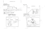
| General Cautions for Maintenance Work | 9-19 | Correct Work, Safety Precautions, Preparations, Cautions for Disassembly and Reassembly, Cautions for Removal and Installation of Hydraulic Equipment |
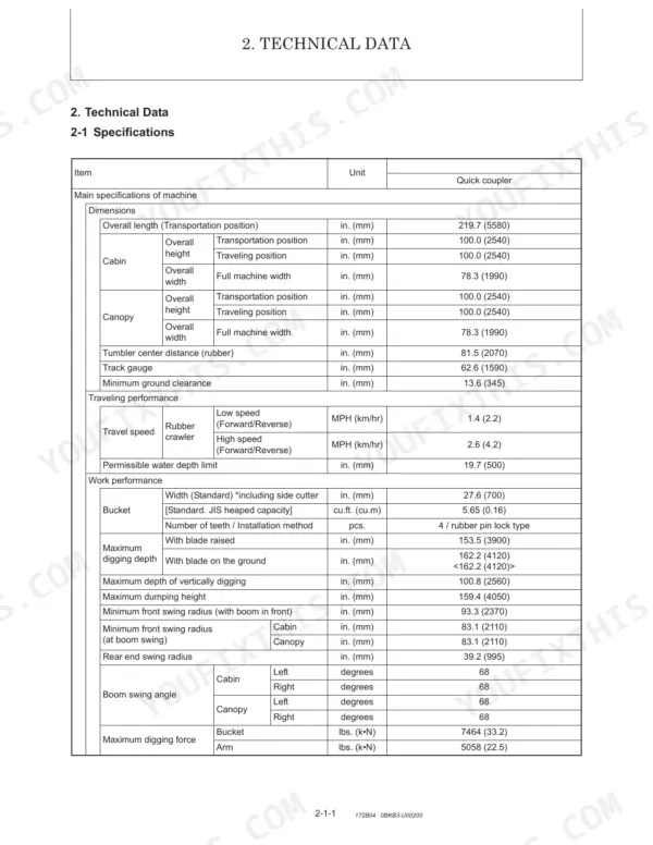
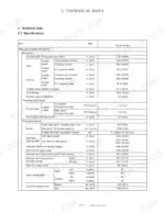
| Technical Data | 20-56 | Specifications, Outline Drawing and Working Area, Weight List of Main Parts, Lifting Capacity List, Specifications for Attachment, Periodic Inspection and Servicing, Fuel |
| Service Standards | 57-91 | Machine Performance, Undercarriage (Rubber Crawler Specifications, Common Specifications of Rubber Crawlers), Controls, Hydraulic Equipment (Hydraulic Cylinders) |
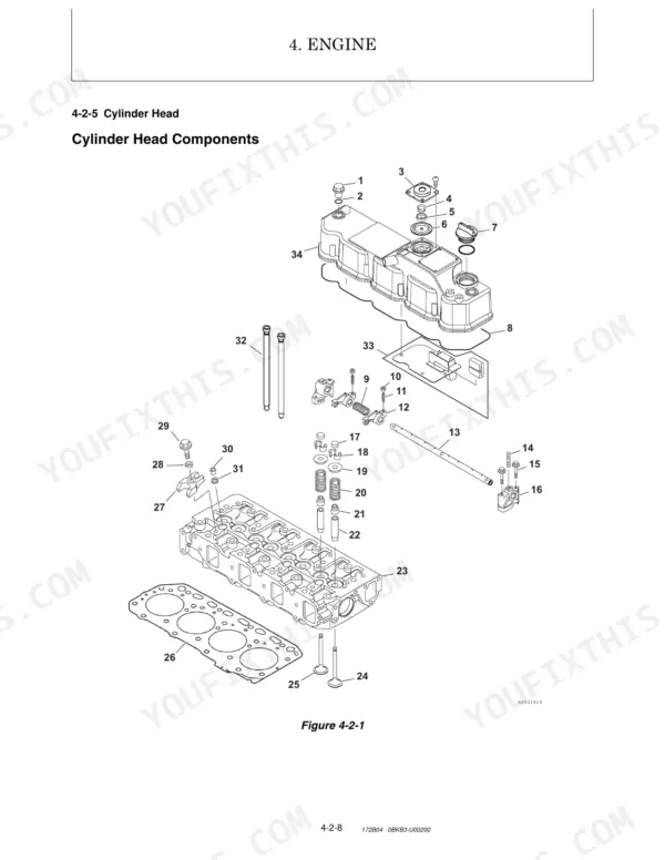
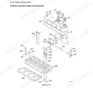
| Engine | 92-274 | Safety (Statements, Precautions), Fuel System (Before You Begin Servicing, System Structure, Specifications, Diagram, Components) |
| Electric System | 275-320 | Electric Equipment of Machine (Parts Layout of Electrical Equipment, Lcd Monitor and Alarm Systems), Circuit Description of Engine Start and Stop |
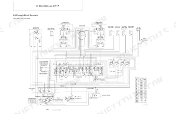
| Hydraulic System | 321-575 | Outline (Control Valve Operation, Additional Operation of Control Valve) |
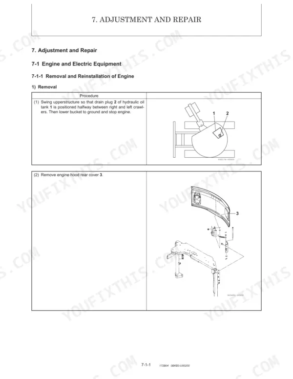
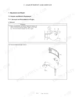
| Adjustment and Repair | 576-743 | Engine and Electric Equipment (Removal Reinstallation: Starter Motor, Radiator and Oil Cooler, Fan Belt and Compressor Driving Belt, Engine ECU, Hydraulic ECU, Diesel Particulate Filter) |
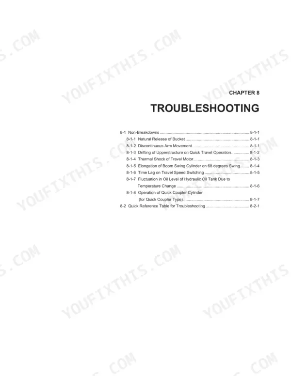
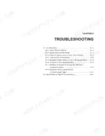
| Troubleshooting | 744-756 | Non-Breakdowns (Natural Release of Bucket, Discontinuous Arm Movement, Drifting of Upperstructure on Quick Travel Operation, Thermal Shock of Travel Motor, Elongation of Boom Swing Cylinder on 68 Degrees Swing, Time Lag on Travel Speed Switching, Fluctuation in Oil Level of Hydraulic Oil Tank Due to Temperature Change, Operation of Quick Coupler Cylinder) |
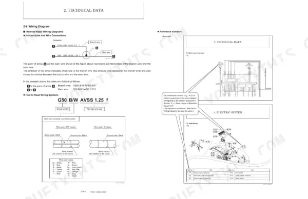
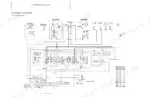
| Appendix | 757-760 | Wiring Diagram |
Documents This Manual Refers To
The manufacturer cites these publications by number. We carry them:
- Yanmar B7-6 Excavator Service Manual (incl. Wiring) (0BKB3-EN0010)
Quick Reference Specifications
| Specification | Value | Page |
|---|---|---|
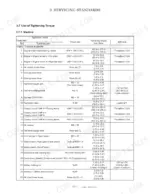
| Travel motor mounting bolt (M14) tightening torque | 138.0 to 151.9 ft•lbf (186.0 to 206.0 N•m) | p. 611 |
| Hydraulic hose recommended working pressure (Code 2) | 2489 to 2986 PSI (17.2 to 20.6 MPa) | p. 16 |
| Hydraulic fitting (M12 x 1.75 parallel pipe thread) tightening torque | 57.9 to 72.3 ft•lbf (78.4 to 98.0 N•m) | p. 84 |
| Hydraulic motor oil seal wear limit | 0.0009843in.(25 µm) or more | p. 495 |
| Allowable clearance for front attachment pins and bushings | 0.04 in. (1.0 mm) | p. 73 |
| Bucket cylinder bottom end pin lock plate tightening torque | 57.9 to 72.3 ft•lbf (78.4 to 98.0 N•m) | p. 79 |
| Track roller & shaft diameter F wear limit | Ø6.14 (156) | p. 67 |
| Track roller mounting bolt (M16×35) tightening torque | 152 to 181 ft•lbf (206 to 245 N•m) | p. 616 |
| Idler & shaft diameter F wear limit | Ø13.15 (334) | p. 68 |
| Idler seal cover (M12×40) tightening torque | 58.0 to 72.3 ft•lbf (78.5 to 98.1 N•m) | p. 613 |
| Hydraulic motor shaft spline wear limit | 0.0009843in.(25 µm) or more | p. 495 |
Manitou America Z55, 550Z Common Problems This Manual Covers
Bucket or coupler will not release
Trouble releasing an attachment or the quick coupler usually points to a fault in the coupler hydraulic circuit or its control valve. The hydraulic chapter details control-valve operation and the additional circuits behind these functions.
Manual Section: Hydraulic System p. 321Travel motor thermal shock
Travel-drive overheating or thermal shock on quick travel can come from a contaminated or overloaded travel circuit or restricted cooling. The troubleshooting chapter lists this among the behaviors to diagnose before condemning the motor.
Manual Section: Troubleshooting p. 744Track tension and undercarriage wear
Poor travel and fast undercarriage wear often trace to track tension that is out of range or worn rollers and idlers. The service standards give rubber-crawler specifications and the roller and idler wear limits.
Manual Section: Service Standards p. 57Hard starting or rough running
An engine that cranks but will not fire, or runs rough, usually points to the fuel system, air in the lines, or an injection fault. The engine chapter covers the fuel system structure, specifications, and components.
Manual Section: Engine p. 92No-crank or monitor alarms
A dead crank or warning lights on the LCD monitor point to the battery, starter circuit, or a sensor fault. The electrical section covers the parts layout, the monitor and alarm systems, and the start and stop circuit.
Manual Section: Electric System p. 275Final drive or travel motor wear
Reduced travel power or a side that drives poorly can trace to travel-motor wear such as a worn shaft spline or oil seal. The adjustment and repair chapter covers removing and reinstalling the travel drive components.
Manual Section: Adjustment and Repair p. 576Frequently Asked Questions
Which machines does this manual fit?
The Manitou Z55 and 550Z compact excavators, form number 50940331, with the 4TNV86CT-PBV engine. The same excavator was sold under the Gehl Z55 and Mustang 550Z names, so this 760-page manual applies to those units too.
What is the torque for the travel motor bolts?
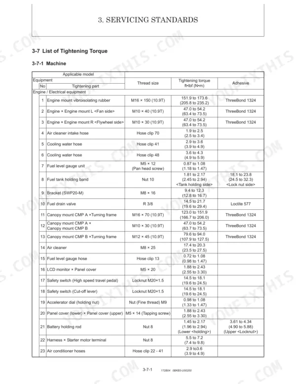
The adjustment and repair section gives the travel motor mounting bolt (M14) torque at 138.0 to 151.9 ft·lbf (186.0 to 206.0 N·m). The service standards chapter lists the rest of the machine torque values. p. 576
Does it include a wiring diagram?
Yes. The appendix at the back of the manual contains the wiring diagram for the machine, and the electrical chapter details the LCD monitor, alarms, and the engine start and stop circuits. p. 757
What format is this Manitou America Z55 manual in?
The complete 760-page searchable Service Manual downloads immediately, ready on any device: the laptop at your desk or your phone in the field.
Can I print just the pages I need from this Manitou America Z55 manual?
Yes. Print individual pages or full chapters for your own shop use, on letter or A4 paper.
Are wiring diagrams part of this Manitou America Z55 Service Manual?
Complete wiring diagrams are included, covering all electrical circuits, harness routing, and connector pinouts for the Manitou America Z55, 550Z.


