Gear box removal and dismantling are worked through in detail in this 474-page Manitou MLT 523 repair manual PDF, which covers four MLT series telehandler variants in one book. Hydraulic circuit diagrams trace the steering, lifting, compensation and jib feed circuits, while wiring diagrams support the electro-proportional control repair section on electric control, hydraulic control and flow rate regulation. Valve bank work runs from disassembly through spool O-ring and intersection seal servicing, the brake chapter takes in the master cylinder and trailer braking system, and the lifting and tilt cylinder chapters finish with seal replacement and refitting. Refill the transmission with 8.5 L of oil and confirm converter intake pressure at 7.5 bar. For a cylinder rebuild, your rod nut figure is 260 to 290 Nm. Bookmarks take you straight to the axle, starter motor or main relief valve pages, and the text layer lets you search a term instead of paging through all 474.
What's Inside This Repair Manual
| System | Pages | Key Topics |
|---|
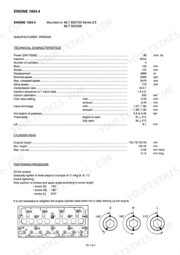
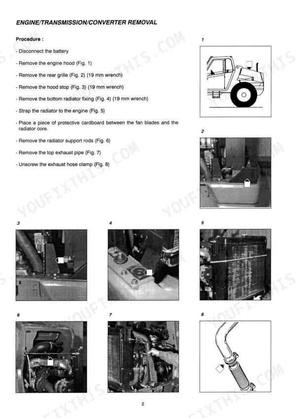
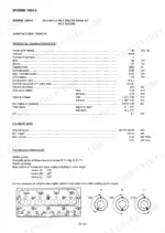
| Engine | 4-17 | Technical Characteristics, Engine Removal |
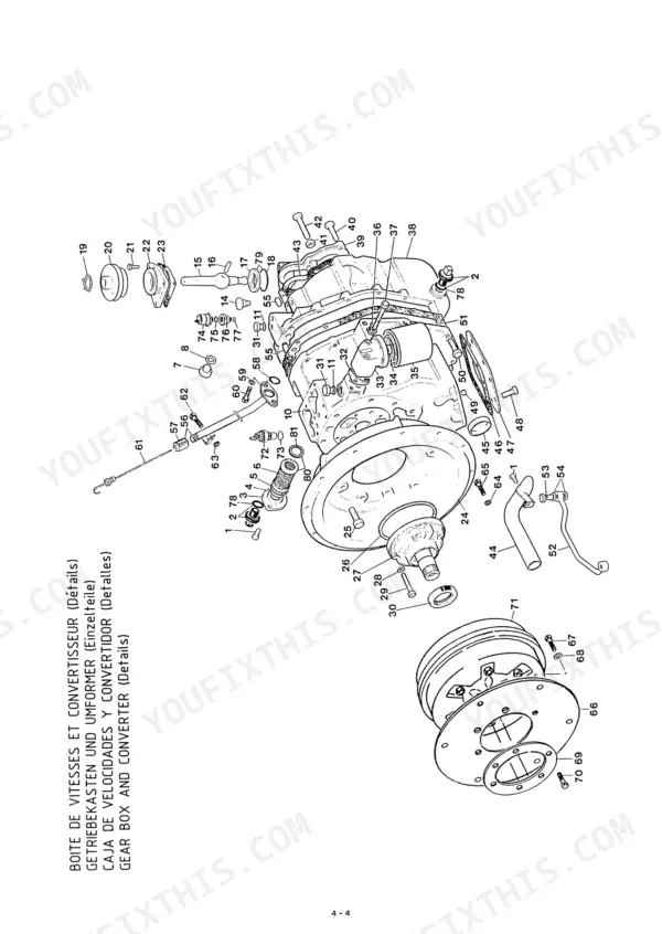
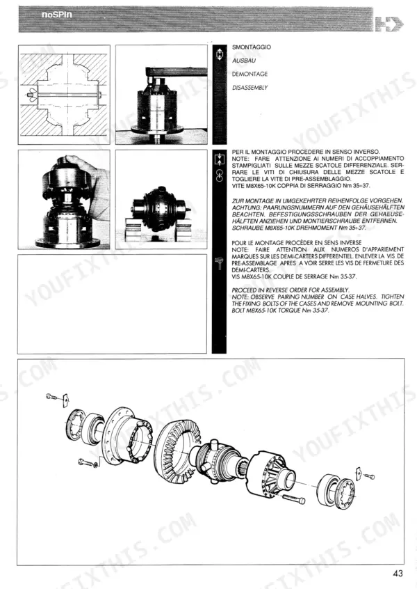
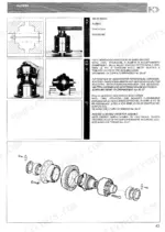
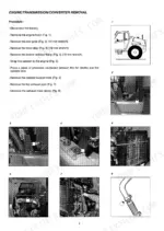
| Transmission | 18-63 | Removal of Gear Box, Dismantling the Gear Box, Transmission Maintenance |
| Brake | 64-83 | Dismantling the Master Cylinder, Trailer Braking System |
| Telescopic Boom | 84-85 | Tilt Cylinder, Attachment Circuit, Telescope Cylinder, Boom Assembly, Compensating Cylinder |
| Axle Assembly - Axle | 86-92 | Dismantling the Boom, Dismantling the Axle |
| Electricity | 93-101 | Dismantling the Starter Motor |
| Valve Bank Dismantling | 102-121 | Valve Bank Disassembly, MLT 626/725, MLT 523/526, Turbo Models |
| Electro-Proportional Control Repair | 122-132 | Basic Principle, Electric Control, Hydraulic Control, Flow Rate Regulation |
| Valve Bank Components and Assembly | 133-141 | Valve Bank Exploded View, Spool O-Ring Servicing, Intersection Seal Servicing, Load Check Valve |
| Lifting Cylinder Dismantling | 142-157 | Lifting Cylinder Disassembly, Refitting, Seal Replacement |
| Tilt Cylinder Dismantling | 158-175 | Tilt Cylinder Disassembly, Refitting, Seal Replacement |
| Pressures and Flow Testing | 176-206 | Pressure Test Bench, Checking Hydraulic Pressure Levels, Main Relief Valve, Compensating Relief Valves |
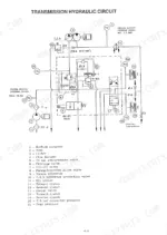
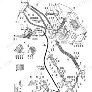
| Hydraulic Diagrams | 207-332 | Hydraulic Circuit Diagrams, Steering Circuit, Lifting Circuit, Compensation Circuit, Jib Feed Circuit |
| Checking Hydraulic Pressure Levels | 333-438 | Hydraulic Circuit Flow Rates, Steering Circuit, Drive Assembly and Intermediate Bracket |
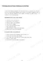
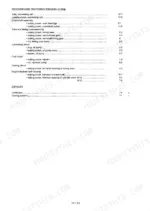
| Basic Electric Circuit | 439-474 | Concept of the Circuit Diagram, Troubleshooting |
Quick Reference Specifications
| Specification | Value | Page |
|---|
| Transmission oil capacity | 8.5 L | p. 92 |
| Transmission oil operating temperature | 85-90°C | p. 42 |
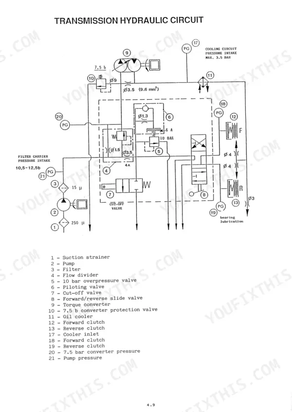
| Converter pressure intake | 7.5 bar | p. 43 |
| Oil pump pressure | 10.5 - 12.6 bar | p. 43 |
| Cylinder rod nut torque | 260-290 Nm | p. 110 |
| Seal preheating temperature | 40-60 °C | p. 110 |
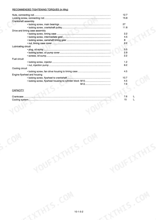
| Engine 1004.4/1004.4 T Crankcase capacity | 7.6 L | p. 9 |
| Engine 1004.4/1004.4 T Cooling system capacity | 15 L | p. 9 |
| Front Axle Differential Oil Capacity | 8.5 L | p. 92 |
| Rear Axle Differential Oil Capacity | 8.5 L | p. 92 |