
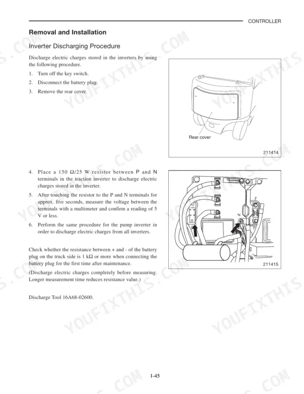
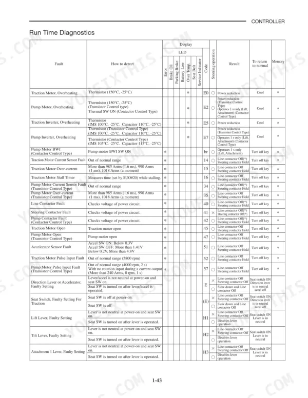
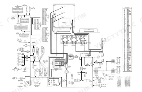
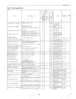
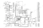
Controller, inverter, and AC traction and pump motors are traced end to end in this 201-page Mitsubishi FBC15N through FBC30LN service manual PDF (OEM ID 99759-7C110), which covers nine variants of the FBC electric forklift truck line. Fault codes E0 through 79 fill nearly half the book, and each one is worked from symptom to fix, from traction motor overheating and line contactor faults to logic card initialize failures. Wiring diagrams show both the contactor and transistor hydraulic control layouts, and the DRS mode and setup option chapters walk you through self-diagnostics and parameter changes on the truck itself. Set the contactor tip gap at 3 ± 0.5 mm, and bring the UVW power cables to 16.0 N·m when the inverter goes back in. Every hour parked on a fault code is a shift's worth of pallets left on the floor. The bookmarked, text-searchable PDF takes you from that flashing code to a truck lifting loads again.
What's Inside This Mitsubishi FBC15N-FBC30LN Manual
| System | Pages | Key Topics |
|---|---|---|
| Controller System | 12-18 | System Configuration, Controller Area Network, Outline of Controller |
| Controller Features | 19-29 | Traction Control Features, Lifting Control Features, Steering Control Features, Diagnosis/Run/Setup Modes, Safety Function, Other Features |
| Setup Option | 30-48 | Details of Setup Options, Setup Options Group 1, Setup Options Group 2 |
| Diagnosis | 49-55 | Outline, Operation Procedure (Self-Diagnostics), Run Time Diagnostics |
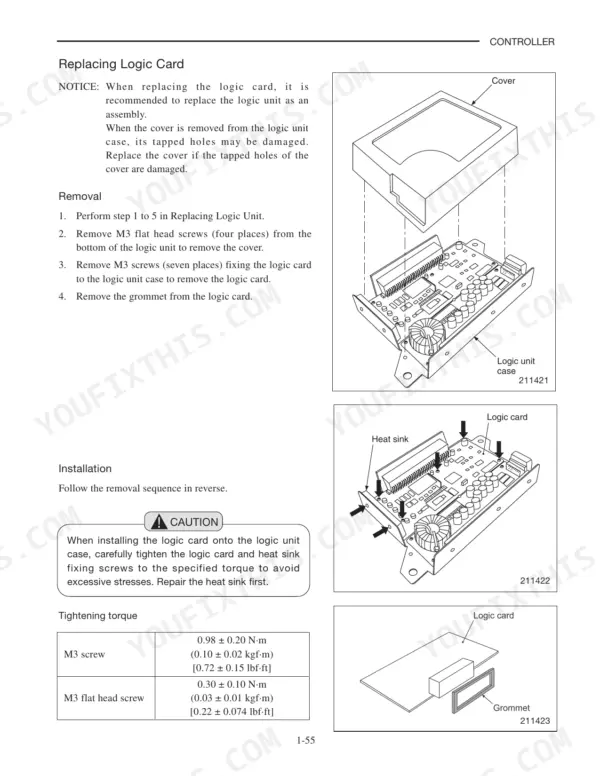
| Removal and Installation | 56-67 | Inverter Discharging Procedure, Replacing Inverter, Insuring Proper Thermal Transfer, Replacing DSP Card, Replacing Logic Unit, Replacing Logic Card, Replacing Power Supply Card |
| Basic Check | 68-74 | Testing Tools, Measurement of Card Voltage, Checking Contactor Coil, Checking Contactor Tip, Checking Inverter, Regeneration Check |
| AC Motor System Basics | 75-76 | Feature of AC Motor, Inverter |
| AC Motor Troubleshooting and Noises | 77 | Clunking, Motor Chatter, Squealing Sound, Low Power |
| Troubleshooting for Control Circuits - General Information | 78-81 | General Information, Replacing Devices, Service Tool Connection, Cleaning Harness Connectors |
| Troubleshooting for Control Circuits - Error Codes E0 to 47 | 82-125 | Traction Motor Overheating, Pump Motor Overheating, Traction Inverter Overheating, Pump Inverter Overheating, Line Contactor Fault, Steering Contactor Fault, Traction Motor Open |
| Troubleshooting for Control Circuits - Error Codes 52 to 79 | 126-172 | Traction Motor Pulse Input Fault, Pump Motor Pulse Input Fault, Display Communication Fault, Logic Card Initialize Failure, Logics Fault, Traction Inverter Fault |
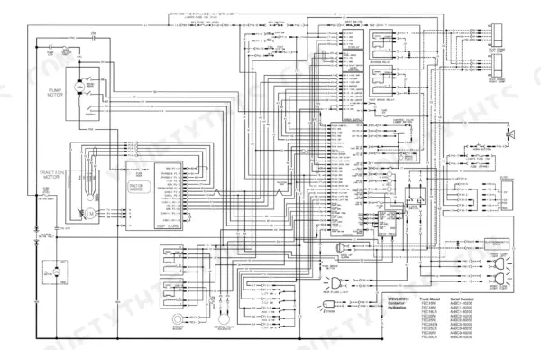
| Electrical Schematics | 173-176 | Wiring Diagrams, Contactor Hydraulics, Transistor Hydraulics |
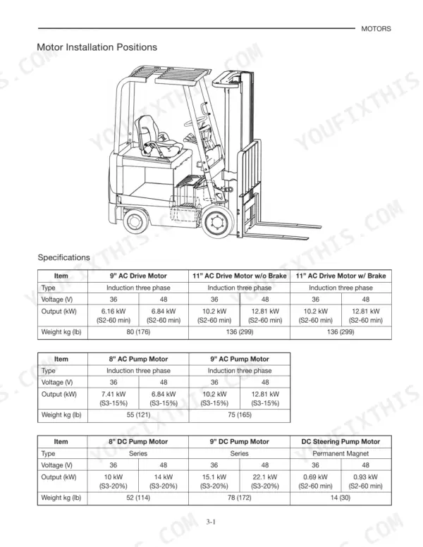
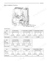
| Motors - Specifications and Installation | 177-187 | Motor Installation Positions, Specifications, Cable Terminal Tightening, Removal and Installation |
| AC Motors - Inspection and Disassembly | 188-191 | External Inspection, Disassembly and Reassembly, AC Drive Motor, AC Pump Motor |
| Trouble Shooting and Service Data for Motors | 192-201 | AC Motor Troubleshooting, DC Motor Troubleshooting, Brush Performance, Commutator Surfaces, Service Data |
Quick Reference Specifications
| Specification | Value | Page |
|---|---|---|
| Motor cable terminal torque, 1 Ton truck (drive & pump) | 11.3 ± 1.1 N·m | p. 185 |
| Motor cable terminal torque, 2/3 Ton truck (drive & pump) | 14.7 ± 1.1 N·m | p. 185 |
| Logic card fixing M3 screw torque (7 places) | 0.98 ± 0.20 N·m | p. 66 |
| Logic unit bottom cover M3 flat head screw torque (4 places) | 0.30 ± 0.10 N·m | p. 66 |
| Contactor tip gap | 3 ± 0.5 mm | p. 72 |
| Accelerator sensor voltage range | 0.2V to 4.8V | p. 127 |
| Accelerator sensor fault trigger (switch open) | 1.41 V or more | p. 127 |
| Thermal sensor resistance | 391 Ω at -30°C (-22°F) to 1407 Ω at 160°C (320°F) | p. 135 |
| CAN resistance between P3-5(92A) and P3-6(93A) | 60 Ω ± 5% | p. 144 |
| 9" AC Drive Motor Weight | 80 kg (176 lb) | p. 179 |
| 11" AC Drive Motor w/o Brake Weight | 136 kg (299 lb) | p. 179 |
| Inverter UVW power cable torque | 16.0 N·m | p. 62 |
Mitsubishi FBC15N-FBC30LN Common Problems This Manual Covers
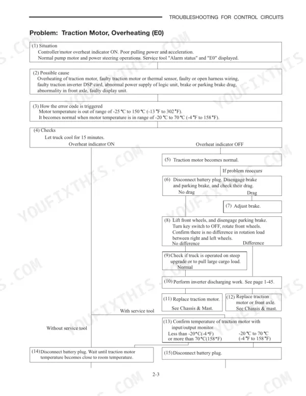
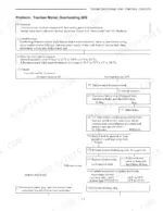
Mitsubishi FBC15N-FBC30LN traction motor overheating, fault E0 stored in memory and read with the service tool
Let the truck cool first. If the overheat indicator stays on, disconnect connector P15 and measure the traction motor thermal sensor at the motor side: 581 Ω at 20°C (68°F), min. 555, max. 607. Then check harness continuity and confirm 14V ± 2V logic unit supply at the traction inverter before replacing the power supply card or the DSP card. If the indicator clears but the fault comes back, check brake and parking brake drag first.
Manual Section: Traction Motor, Overheating (E0) p. 83Hydraulic pump motor overheating on transistor control trucks, fault E2 stored in memory
If the overheat indicator clears and the fault comes back, check gear pump oil pressure and the hydraulic lines following page 85, and repair the pump or piping if abnormal. If the indicator stays on, test the pump motor thermal sensor and its harness before you suspect the pump inverter DSP card.
Manual Section: Pump Motor, Overheating (E2) p. 85Line contactor fault, code 40 on the display, all truck operations inhibited
Cycle the power and confirm code 40, then check line contactor operation in self-diagnosis mode following page 113. Depending on the result, compare the inverter DC voltages and replace the traction or pump inverter, or check the contactor tip and measure the coil: 44 at -30 C(-22 F) to 65 at 80 C(176 F). Check the harness before replacing the logic card.
Manual Section: Basic Check p. 113Traction inverter overheating, fault E5 stored in memory
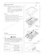
When a traction inverter goes back in, prepare the vehicle mounting surface: its flatness should match the control surface (0.005" per linear inch). Remove rust, scale, weld splatter or paint, and apply thin, even thermal paste so heat can leave the inverter.
Manual Section: Traction Inverter, Overheating (E5) p. 59Traction motor over-current fault, code 15 on the display
Check the traction motor and terminals for burning, the U, V and W cable connections, the DSP flat cable, and the speed sensor connector and harness following page 103. Secure or repair what is loose before replacing the inverter.
Manual Section: Traction Motor, Over-current (15) p. 103Pump motor worn brushes, code br on the display (contactor control type only)
Disconnect the brush wear detector wires at the pump motor and recheck the code following page 99. If br clears, inspect and replace the brushes; if it stays, check the wiring to the logic unit and repair it, or replace the logic card.
Manual Section: Trouble Shooting and Service Data for Motors p. 99Frequently Asked Questions
How do you clear the error code on a Mitsubishi FBC electric forklift?
To review and clear fault data, use the Run Time Diagnosis mode. After reviewing all fault data, 'donE' will appear on the display. To delete all stored fault data, move the DRS switch from the D position to the R position and then to the S position. When deletion is complete, 'donE' will flicker on the display. p. 51
What is the tightening torque for the high-power motor cable terminals on a 1-ton Mitsubishi FBC15N-FBC30LN truck?
For a 1-ton truck, the tightening torque for the high-power motor cable terminals is 11.3 ± 1.1 N·m (1.2 ± 0.1 kgf·m) [8.33 lbf·ft]. p. 185
What is the specified contactor coil resistance range on the Mitsubishi FBC15N-FBC30LN?
The contactor coil resistance must be 44 ohm at -30°C (-22°F) to 65 ohm at 80°C (176°F). If the measured value deviates from this range, replace the contactor assembly. p. 72
What is the recommended interval for checking or replacing the inverters on the Mitsubishi FBC15N-FBC30LN?
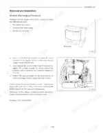
It is recommended to check or replace the inverters every 10,000 hours of service operation. p. 62
What is the nominal gap for the contactor tips on the Mitsubishi FBC15N-FBC30LN?
The gap at each contactor tip must be 3 ± 0.5 mm (0.12 ± 0.02 in.). p. 72
How is this Mitsubishi FBC15N Service Manual delivered?
Delivery is instant: a 201-page searchable PDF is yours the second checkout clears. Laptop, tablet, or phone, all fine.
Is this Mitsubishi FBC15N manual print-friendly?
Yes. Print the sections you need to take out to the shop for your own use. Standard letter or A4 paper works.

Reviews
There are no reviews yet.