
Part of the New Holland Operator Manuals.
Setting up, running and servicing a New Holland TL series tractor properly is what 258 pages under OEM ID 6036457100 buy you, with all four models in the range covered. This New Holland TL90 operator manual PDF walks through every control and gauge, then gives much of the book to the range, shuttle and creeper transmissions, speed tables, power shuttle fault codes and the electronic lift. Lubrication and maintenance fill about a fifth of it, built around an interval table, and troubleshooting charts sort faults by engine, electrics, hydraulics and brakes. Set the clutch pedal 185 mm off the platform on a cabless tractor (162 mm with a cab), and torque the 4WD front hub locknuts to 255 Nm. Alone in the yard with the tractor, there's nobody to ask. Bookmarked chapters and a keyword-searchable text layer take you straight to the right page, so your TL runs again before the weather turns.
What's Inside This New Holland TL70, TL80, TL90, TL100 Operator Manual
| System | Pages | Key Topics |
|---|---|---|
| General Information | 1-8 | Communications for the User, Tractor Identification, Ecological Considerations |
| Safety Regulations | 9-23 | Working Safely, Safety Decals, Standardised Symbols, Tractor Noise Level Information |
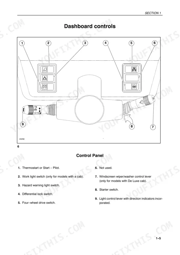
| General Information, Controls and Instruments | 24-37 | Safety Covers and Guards, Controls and Instruments Position and Function |
| Before Using the Tractor | 38-41 | Running-In Period, Starting the Engine, Starting with Low Temperatures, Starting with Thermostart, Starting with Start-Pilot |
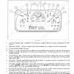
| Instrument Panel and Digital Display | 42-50 | Function Indicators, Coolant Temperature Gauge, Fuel Gauge, Instrument Calibration, Entering Implement Width, Slip Control |
| Transmission Systems | 51-71 | Range Gear Transmission, Shuttle Transmission, Creeper Transmission, Overdrive Transmission, Speed Tables |
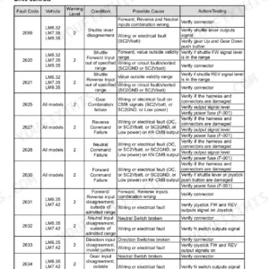
| Power Shuttle and Clutch Calibration | 72-78 | Electro-Hydraulic Power Shuttle, Clutch Calibration, Fault Code Display, Fault Codes Description |
| Hydraulic Lift and Linkage | 79-123 | Transmission Disabled Indicator, Power-Shuttle Fault Codes, Electronic Lift Controls, Three-Point Linkage, Towing Equipment, Towing Hitch |
| Roll Bar and Wheel Track Adjustment | 124-139 | Fold-Down Roll Bar, Three-Point Linkage Points, Wheel Track Adjustment, Front 4WD Wheel Tracks |
| Tyre Maintenance and Specifications | 140-173 | Tyre Maintenance, Tyre Data and Pressures, Tyre Combinations, Cab Air Conditioning, Cab Maintenance |
| Lubrication and Maintenance | 174-225 | Lubrication and Maintenance Table, Flexible Maintenance |
| Troubleshooting | 226-233 | Engine, Electrical System, Hydraulic System, Hydraulic Lift, Brakes, Cab |
| Specifications and Data | 234-249 | Engine, Transmission, Hydraulic Lift, Steering, Brakes, Electrical System |
Quick Reference Specifications
| Specification | Value | Page |
|---|---|---|
| 4WD front wheel hub disk locknuts tightening torque | 255 Nm (26 kgm) | p. 136 |
| 4WD front wheel rim disk locknuts tightening torque | 245 Nm (25 kgm) | p. 136 |
| Engine/gearbox clutch pedal distance from platform (tractors without cabs) | 7.28 in (185 mm) | p. 180 |
| Engine/gearbox clutch pedal distance from platform (tractors with cabs) | 6.37 in (162 mm) | p. 180 |
| Fan belt tension (version without cab and with non-air conditioned cab) | 0.39 to 0.43 in (10 to 11 mm) with a load of 78 to 98 N (8 to 10 kg) | p. 181 |
| Fuel filter cartridge tightening | 3/4 of a turn by hand | p. 195 |
| Injection pump protection | 10% PROT 10 W/M oil in fuel | p. 205 |
| Pressure relief valve setting | 2756 psi (190 bar) | p. 240 |
| Fuel injectors calibration (TL70, TL100) | 230 to 238 bar (3336 to 3452 psi) | p. 237 |
| Fuel injectors calibration (TL90) | 260 to 272 bar (3771 to 3945 psi) | p. 237 |
| Engine injection pump timing (TL70) | 4° ± 1° Before TDC | p. 237 |
| Fuel tank capacity (TL70, TL80) | 115 litres | p. 175 |
New Holland TL70, TL80, TL90, TL100 Common Problems This Manual Covers
New Holland TL70 to TL100 three-point linkage lift capacity low or lowering speed wrong with draft control
Check linkage movement, lift capacity and lowering speed against the hydraulic lift troubleshooting chart in the section beginning on page 226. Verify the electronic lift control settings and draft control operation described in the Hydraulic Lift and Linkage section on page 79 before suspecting the hydraulics. Set the controls right first, then look for parts.
Manual Section: Hydraulic Lift and Linkage p. 79Coolant temperature gauge reading high and engine overheating with loose fan belt
Check the coolant temperature gauge reading described on page 42, then work through the engine overheating checks in the troubleshooting section starting on page 226. Measure fan belt deflection following page 181: 10 to 11 mm (0.39 to 0.43 in) under a 78 to 98 N (8 to 10 kg) load on tractors without a cab or with a non-air conditioned cab.
Manual Section: Lubrication and Maintenance p. 181Engine hard to start or will not start in low temperatures with Thermostart or Start-Pilot
Follow the low temperature starting procedure in Before Using the Tractor on page 38, and use Thermostart or Start-Pilot only as that section directs for your tractor. If it still won't fire, work through the engine no-start checks in the troubleshooting section starting on page 226 before you flatten the batteries with repeated cranking.
Manual Section: Before Using the Tractor p. 38Power shuttle fault code shown on display with transmission disabled indicator lit
Check the code on the display against the fault codes description in the Power Shuttle and Clutch Calibration section on page 72. Verify what the transmission disabled indicator means in the Hydraulic Lift and Linkage section starting on page 79. Where the section calls for it, run the clutch calibration procedure before you replace any parts.
Manual Section: Power Shuttle and Clutch Calibration p. 72Engine gearbox clutch pedal on cab or non-cab tractor sitting out of specified distance from platform
Measure the engine/gearbox clutch pedal distance from the platform following page 180: 185 mm (7.28 in) on tractors without cabs, 162 mm (6.37 in) on tractors with cabs. Adjust it back to that figure as the maintenance section describes. If the power shuttle shows a fault code afterward, run the clutch calibration from page 72.
Manual Section: Lubrication and Maintenance p. 180Battery charge light stays on after engine starts and batteries not charging
Check what the battery charge light means in the function indicators on page 42, then follow the electrical system troubleshooting checks for batteries not charging and low starter speed in the section starting on page 226. If the alternator is suspect, make sure any replacement matches the 540 W rating listed on page 244 before you head back to the field.
Manual Section: Electrical System TroubleshootingFrequently Asked Questions
What are the torque specifications for the front wheel hub locknuts on the New Holland TL70?
The tightening torque for the wheel-hub locknuts on the New Holland TL70 is 115 Nm (11.7 kgm). p. 134
How do I interpret the fault codes on a New Holland TL90 or TL100 tractor?
The fault code indicator identifies error codes in six phases, starting with 5 rapid flashes, followed by a 2-second pause, then flashes for the first digit, a 1-second pause, flashes for the second digit, and a 3-second pause. A detailed list of fault codes and their meanings can be found in the 'FAULT CODES DESCRIPTION' tables on pages 76-78. p. 80
What is the procedure for adjusting the engine/gearbox clutch on a New Holland TL series tractor?
To adjust the clutch, ensure distance A on the pedal is 7.28 in (185 mm) for tractors without cabs, or 6.37 in (162 mm) for tractors with cabs. Loosen the locknut (1) and adjust the nut (2) counter-clockwise until the distance is correct, then re-tighten the locknut. p. 180
What is the fuel tank capacity for the New Holland TL90 and TL100 models?
The fuel tank capacity for the New Holland TL90 and TL100 models is 35.66 gallons (135 litres). p. 175
What is the correct valve clearance for the engine valves on the New Holland TL series?
The valve clearance for both intake and exhaust valves, measured when the engine is cold, is 0.012 ± 0.002 in. (0.30 ± 0.05 mm). p. 198
Is this New Holland TL70–TL100 Series Operator Manual a digital download?
Instant PDF download. You get the full 258-page searchable Operator Manual immediately after payment. Open it on your laptop, tablet, or phone right in the shop.
Can I print a copy of this New Holland TL70–TL100 Series manual for the shop?
Print away. There is no DRM and no page limit. Many buyers print one chapter at a time and leave the rest on a tablet.






Reviews
There are no reviews yet.