
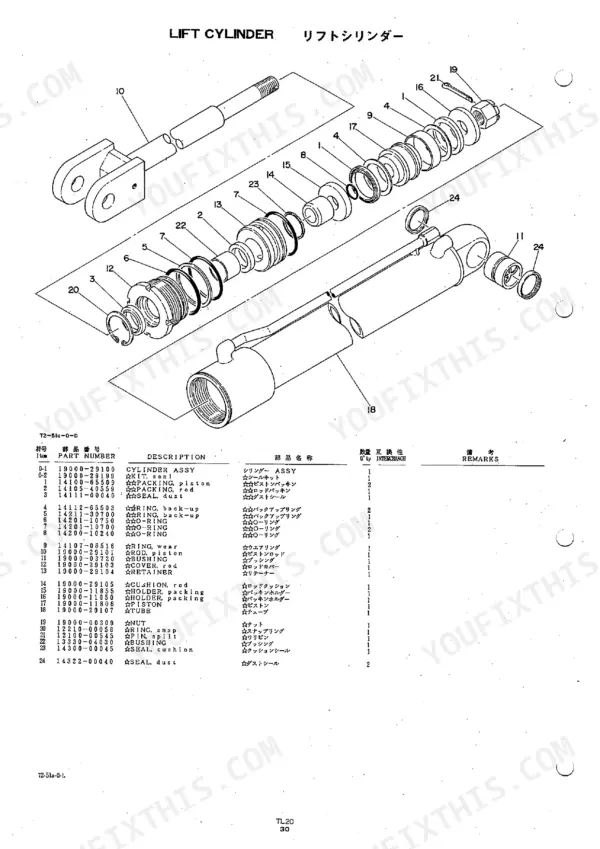
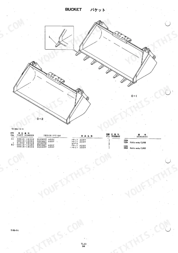
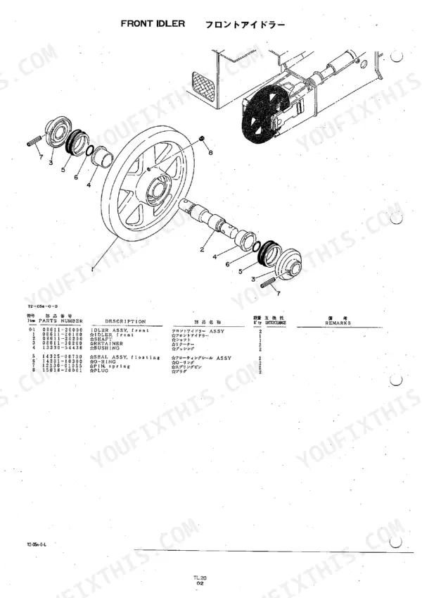
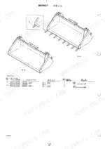
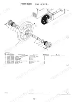
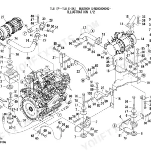
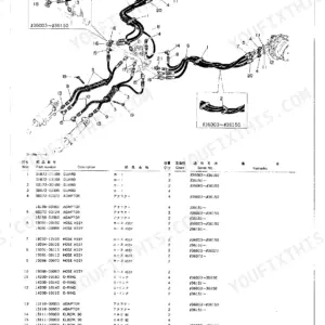
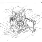
Part number arguments end at the Takeuchi TL20 parts catalog PDF, factory publication PUB. 1, 82 pages built around the TL20 crawler loader. Exploded drawings break the machine down the way it comes apart: track roller, front idler, track spring and travel device through the lower machinery group, then control valve, solenoid valve, lift and bucket cylinders, travel motor and both hydraulic pumps under hydraulic device. Callout numbers tie straight to part numbers and quantities, so you order the right bucket cylinder seal or pump drive fastener the first time. Option coverage runs to the 4-In-1 bucket, clam cylinder, cylinder lock and heater; the arm group separates assembly hardware from arm piping, and sticker and tool listings sit in their own section. Every hour that loader sits is an hour it is not moving material. Bookmarked and searchable, bought once and yours for as long as the TL20 is in your yard.
What's Inside This Takeuchi TL20 Parts Manual
| System | Pages | Key Topics |
|---|---|---|
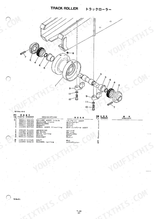
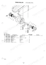
| Lower Machinery | 15-22 | Track Roller, Front Idler, Track Spring, Travel Device, Frame |
| Upper Machinery 1 | 23-28 | Travel Lever, Operation Pedal |
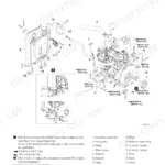
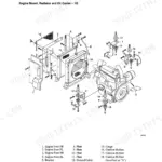
| Upper Machinery 2 | 29-34 | Engine & Accessories, Control Box, Engine Control, Electrical |
| Upper Machinery 3 | 35-44 | Piping 1, Piping 2, Piping 3, Pump Drive, Hydraulic Tank, Fuel Tank |
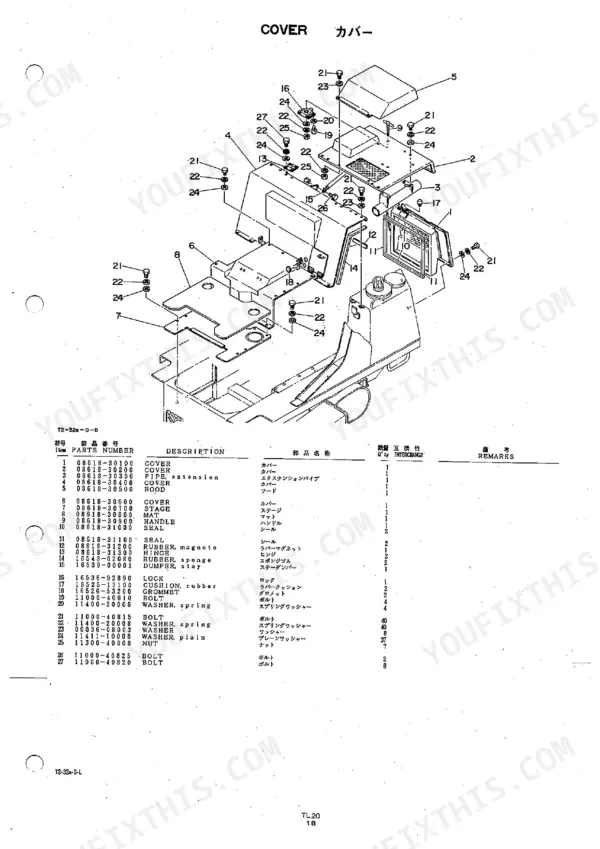
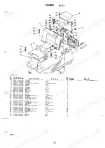
| Upper Machinery 4 | 45-52 | Cover, Seat, Cabin 1, Cabin 2, Canopy |
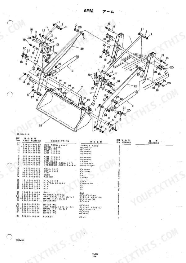
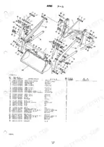
| Arm | 53-56 | Assembly, Piping Arm |
| Others | 57-60 | Sticker, Tool |
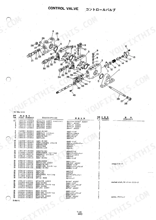
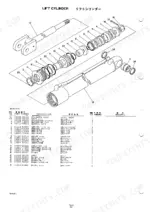
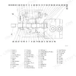
| Hydraulic Device | 61-72 | Control Valve, Solenoid Valve, Lift Cylinder, Bucket Cylinder, Travel Motor, Hydraulic Pump, Hydraulic Pump Sub |
| Option | 73-82 | Heater, Bucket, 4-In-1 Bucket, Cylinder Lock, Clam Cylinder |
Takeuchi TL20 Common Problems This Manual Covers
Takeuchi TL20 hydraulic filter part number unclear, several aftermarket listings show different element sizes
Check the hydraulic tank breakdown starting on page 41, where the tank assembly, breather, and filter are called out as separate line items. Match the callout number on the exploded view to the parts list entry, then confirm your machine serial falls inside the listed range before ordering any of the 4 filter elements shown.
Manual Section: Hydraulic Tank Maintenance p. 41Need seal kit numbers for lift cylinder and bucket cylinder rebuild, rods weeping at the gland
Pull up the Hydraulic Device diagrams on page 63 and page 66. Lift cylinder and bucket cylinder are drawn as separate exploded views with rod, gland, piston, and seal items numbered individually. Note both cylinder callouts before ordering, since the 2 cylinders do not share the same gland seal number on this loader.
Manual Section: Hydraulic Device p. 63Cannot identify which hose assembly and adapter fittings run from the loader valve to the arm
Start at the Piping breakdown in Upper Machinery 3 on page 37, which splits hose assemblies, adapters, and fittings across Piping 1, 2, and 3. Then jump to the arm piping view on page 55 to pick up the run past the pivot. Record all 3 piping group numbers so you order matching ends.
Manual Section: Hydraulic Piping Systems p. 55Undercarriage wearing out, unsure which track roller and front idler numbers fit this machine
Open the Lower Machinery chassis diagrams on page 17 and page 18. Track roller, front idler, and track spring are listed with individual quantities per side, so count what your undercarriage actually carries before ordering. Verify the travel device callout on page 19 too, since roller numbers change across serial ranges.
Manual Section: Lower Machinery p. 17Fuel lift pump replacement needed but tank strainer and fuel line numbers not listed together
Go to the Upper Machinery 3 group on page 35 and find the fuel tank breakdown covering tank, cap, strainer, float, and fuel lines. Each item carries its own number, so order the strainer and line separately from the pump. Cross-check the 2 line lengths against what is routed on your machine.
Manual Section: Fuel System p. 35Replacing a worn 4-in-1 bucket cylinder, unclear whether option parts are in the main listing
Check the Option group starting on page 73, which carries heater, bucket, 4-in-1 bucket, cylinder lock, and clam cylinder as their own breakdowns. The attachment view on page 76 shows the clam cylinder items numbered separately from the standard bucket, so confirm which of the 2 bucket styles your machine runs.
Manual Section: Option p. 73Frequently Asked Questions
What is the part number for the hydraulic filter?
The hydraulic filter for the TL20 is part number 15560-00020. p. 41
What is the part number for the fuel tank cap?
The fuel tank cap for the TL20 is part number 15521-00200. p. 43
What is the part number for the pilot lamp on the control box?
The pilot lamp for the control box is part number 17005-10001. p. 32
What is the part number for the horn?
The horn for the TL20 is part number 17035-00312. p. 34
What is the part number for the grease nipple on the track spring assembly?
The grease nipple for the track spring assembly is part number 15600-01000. p. 19
How will I receive this Takeuchi TL20 Parts Catalog?
You download the Parts Catalog yourself: 82 pages, searchable PDF, available immediately. Keep a copy on every device you use.
Can I print a copy of this Takeuchi TL20 Parts Catalog for the shop?
Yes. Print the pages or sections you need for your own shop use. Any standard printer works.
Reviews
There are no reviews yet.