
Takeuchi's TW60 service manual (OEM 8015739) takes the TW60 wheel loader apart across 246 pages, splitting front and rear carriage at the pendulum joint and working through hoisting gear, hydraulics, electrics, diesel engine, axles, drum brakes and cab. Hydraulics fill the largest share of this Takeuchi TW60 service manual PDF: a circuit diagram traces oil from the travel and charge pumps through the pressure relief valve, steering unit and brake cylinder, and the adjustment chapter shows you how to set charge, travel, loading circuit and steering pressures. Electrical circuit diagrams map the ignition lock, starter, generator, preheating relay and lighting, while fault tables for each system pair a symptom with its cause. On an M18x1.5 hose fitting, bring the DKL nut to 30-35 Nm; the hoisting gear locking screws take 120 Nm. Sometimes it's just you, the loader and nobody to phone. Bookmarked and text-searchable, the PDF rides on your laptop or phone to wherever the TW60 is parked.
What's Inside This Takeuchi TW60 Manual
| System | Pages | Key Topics |
|---|---|---|
| Preface | 3-4 | Safety Regulations, Operating Instructions |
| Introduction | 9-22 | User Information on the Service Manual, Breakdown of Assembly Groups and Chapter Overview, Technical Description of the Wheel Loader |
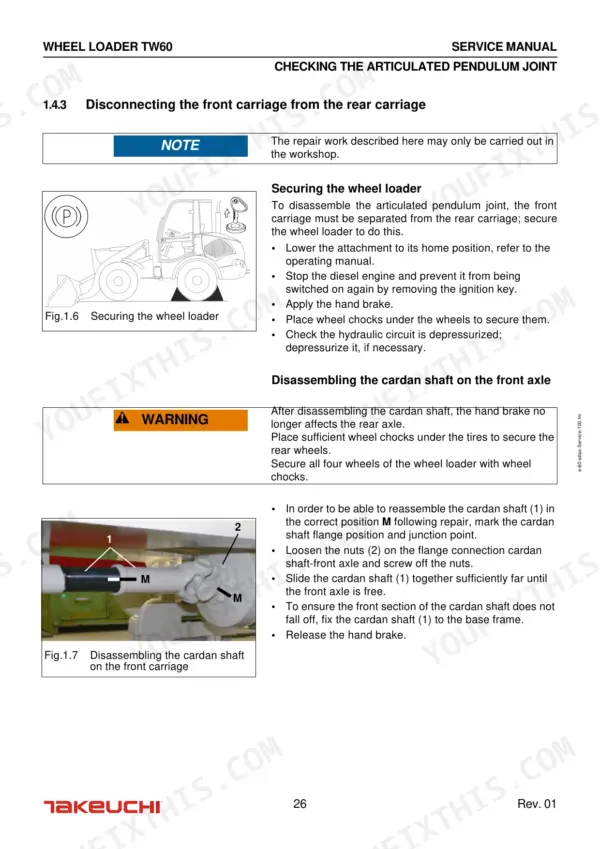
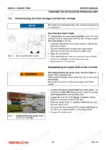
| Front and Rear Carriage | 23-46 | Front Carriage, Repairing the Front Carriage |
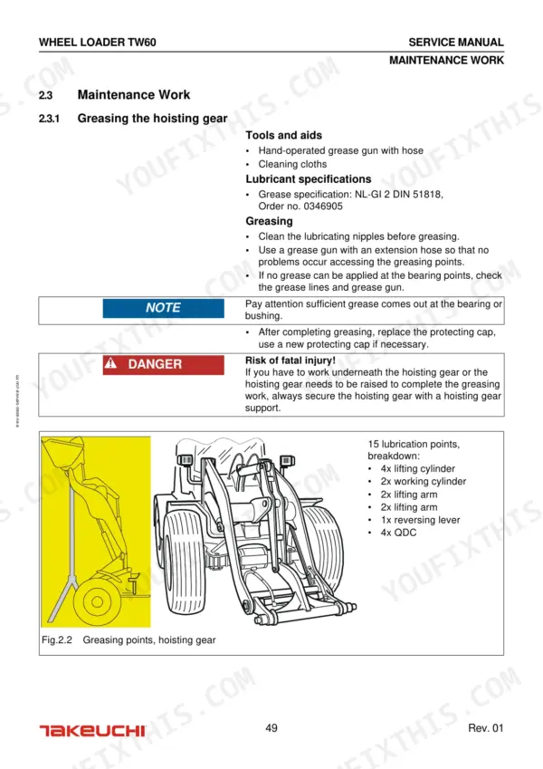
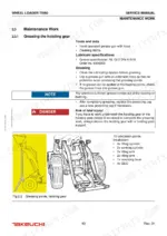
| Hoisting Gear and Hoisting Gear Hydraulics | 47-58 | Operating Faults and Solutions, Maintenance Work (Greasing the Hoisting Gear) |
| Breakdown of Assembly Groups | 59 | Hydraulic System, Hydraulic Circuits, Main Assemblies |
| Technical Data | 59 | Hydraulic Unit, Travel Motor, Steering Unit |
| Faults, Causes and Corrective Measures | 60-64 | Hydraulic Oil Supply, Travel Circuit, Loading Circuit Pressure, Steering Circuit, Electrical System, Diesel Engine |
| Setting Instructions, Hydraulic System | 65-68 | Operating Conditions for Correct Measurement Results, Measuring and Test Instruments, Safety Regulations, Measurement and Adjustment Work, Environmental Protection Measures |
| Completing Adjustments | 69-84 | Diesel Engine Idle Speed, Charge Pressure, Travel Pressure, Loading Circuit Pressure, Steering Circuit Pressure, End Speed |
| Completing Repairs | 85-108 | Completing Repairs to the Travel Pump, Repairing the Load Pump, Repairs to the Charge Pump, Repairs to the Pump Set and Travel Pump |
| Repairing the Loading Circuit | 109-118 | Repairing the Loading Circuit Control Block |
| Repairing the Hydraulic Cylinders | 119-132 | Checking the Steering Cylinder, Checking the Lifting and Working Cylinder, Checking the QDC Hydraulic System, Venting the QDC Hydraulic System |
| Repairing the Steering Circuit | 133-136 | Repairing the Steering Unit |
| Repairing the Hydraulic Components | 137-144 | Repairing the Inching Valve, Repairing the Differential Lock Control Block, Checking the Hydraulic Oil Cooler (Combined Cooler) |
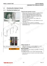
| Checking the Hydraulic Circuit | 145-154 | Checking the Hydraulic Oil, Venting the Hydraulic Circuit, Operating the Vacuum Pump, Rinsing the Hydraulic Circuit |
| Table of Figures | 155-158 | Assembly Groups, Hydraulic Connections, Steering Cylinder, Cardan Shaft, Electrical Installations, Lighting |
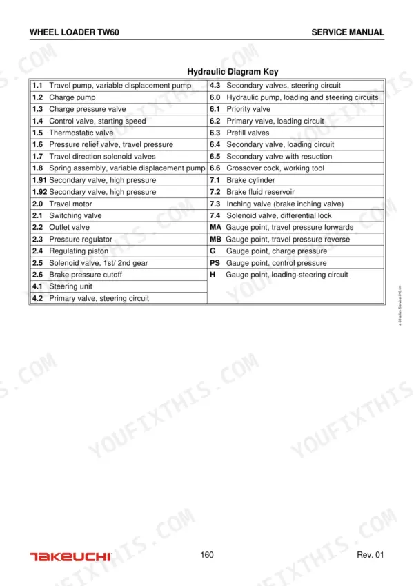
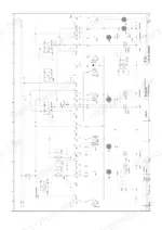
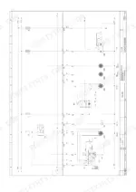
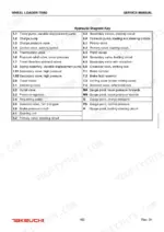
| Appendix to Chapter 3: Hydraulic System Circuit Diagram | 159-162 | Travel Pump, Charge Pump, Pressure Relief Valve, Steering Unit, Brake Cylinder, Solenoid Valve |
| Electrical System | 163-180 | Operating Faults and Solutions, Service and Maintenance Work (on the Battery, Checking the Electrical System), Setting Instructions |
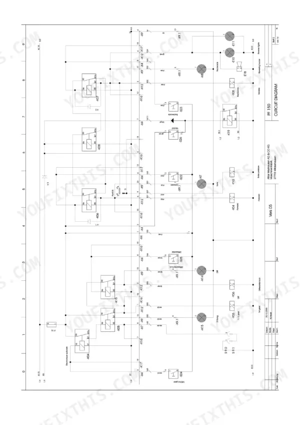
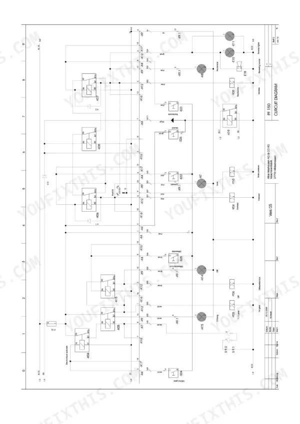
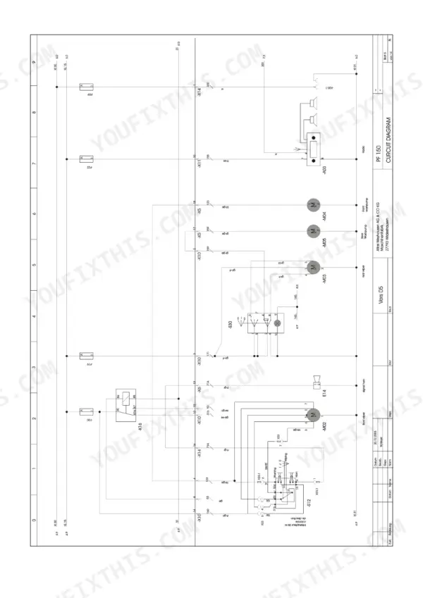
| Appendix to Chapter 4: Electric System Circuit Diagrams | 181-192 | Ignition Lock, Starter Motor, Generator, Preheating Relay, Lighting System, Air Conditioning Unit |
| Diesel Engine | 193-210 | Technical Data (Fuel, Engine Oil), Faults, Causes, Solutions (Faults, Causes and Solutions Related to the Diesel Engine) |
| Axles and Brakes | 211-238 | Operating Faults and Solutions, Maintenance Work, Axles and Drum Brake (Lubricants and Filling Quantities, Checking the Oil Level Axle, Checking and Changing the Brake Fluid) |
| Operator's Cab | 239-246 | Breakdown of Assembly Groups, Cleaning and Maintenance Work, Replacing the Operator's Seat, Table of Figures, Table of Topics |
Quick Reference Specifications
| Specification | Value | Page |
|---|---|---|
| Locking screws torque | 120 Nm | p. 55 |
| Tightening torque for L-series hose connections (Tube A. Ø 6, DN 5, M12x1.5) | 10-12 Nm (DKL), 8-10 Nm (DKOL) | p. 18 |
| Tightening torque for L-series hose connections (Tube A. Ø 8, DN 6, M14x1.5) | 12-15 Nm (DKL), 10-13 Nm (DKOL) | p. 18 |
| Bearing journal (5) to retaining disk (3) screw torque | 120 Nm | p. 33 |
| Bearing retaining disk (1) screw torque | 50 Nm | p. 33 |
| Charge pressure | 23-25 bar | p. 71 |
| Travel pressure | 420 +20 bar | p. 69 |
| Air filter cleaning pressure | 6 bar | p. 200 |
| Standard hydraulic oil filling quantity | 60 L | p. 152 |
| Optional hydraulic oil filling quantity | 60 L | p. 152 |
| Battery voltage | 12 Volt | p. 163 |
| Battery capacity | 88 Ah | p. 163 |
Takeuchi TW60 Common Problems This Manual Covers
Takeuchi TW60 hydraulic oil supply running hot, cooler soiled and oil temperature slow to drop
Clean the soiled combined cooler first, then check the hydraulic oil cooler following page 137 and test for a defective temperature sensor before trusting the gauge. Walk every hydraulic line for leaks while the panels are off. If you drain the system, refill with the 60 L standard filling quantity listed on page 152.
Manual Section: Hydraulic Oil Supply Faults p. 60Loader travels in one direction only, moves sluggishly, or has poor acceleration and road speed
Measure charge pressure before you blame the travel pump; it should hold 23 to 25 bar per page 71. Then check travel pressure against 420 +20 bar on page 69 and confirm the forward/reverse starting speed of 1250 to 1300 min-1 following page 74. Low readings send you to the travel pump repairs from page 85.
Manual Section: Travel Circuit FaultsHoisting gear sinks on its own, automatic tipping occurs, or loading circuit has no working power
Measure loading pressure following page 80: expect 12 to 20 bar with no loading movement and 225 to 235 bar with loading movement. If pressure is missing or low, or the hoisting gear drifts down under load, work through the loading circuit control block repair starting on page 109 before you pull any cylinders.
Manual Section: Loading Circuit Pressure FaultsSteering on the articulated loader turns slow, works intermittently, or fails completely
Test steering circuit pressure following page 82 and compare it against 170 to 185 bar. Check the priority valve for a malfunction before you condemn anything else in the circuit. If pressure reads good but steering still lags, repair the steering unit following page 133 and check the steering cylinder starting on page 119.
Manual Section: Steering Circuit FaultsArticulated pendulum joint makes noise at full lock and moves jerkily through its angle
Inspect the articulated pendulum joint bearings following the front carriage repair section on page 23. Confirm the joint swings smoothly through its ±12° angular movement listed on page 12. When reassembling, torque the bearing journal to retaining disk screws to 120 Nm and the bearing retaining disk screws to 50 Nm per page 33.
Manual Section: Front and Rear Carriage p. 23Hoisting gear shows lateral play and noise while lifting cylinders move sluggishly
Grease the hoisting gear bearing points per the maintenance schedule on page 49, then recheck for lateral play and listen for the noise again. Torque the locking screws to 120 Nm as given on page 55. If the cylinders stay sluggish after that, check the lifting and working cylinder following page 119.
Manual Section: Hoisting Gear and Hoisting Gear Hydraulics p. 47Frequently Asked Questions
How do you bleed the hydraulic system on a Takeuchi TW60?
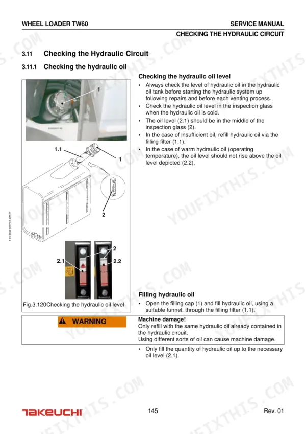
To bleed the hydraulic system, use a vacuum pump to generate pressure in the hydraulic oil tank. Open the charge pressure connection PS on the travel pump to vent the circuit, repeating until no more air escapes. For the loading circuit, start the engine and perform short loading movements repeatedly until the system is vented. p. 147
What are the torque specifications for the Takeuchi TW60 wheel loader?
Torque specifications vary by component. For example, the cardan shaft nuts require 90 Nm, the articulated pendulum joint retaining disk screws require 50 Nm, and the hoisting gear locking screws require 120 Nm. Refer to the specific tables in section 0.9 for metric headless screws and RIPP screws. p. 18
How do you check the hydraulic pressure on a Takeuchi TW60?
Hydraulic pressure is checked using analogue pressure gauges (0-60 bar or 0-600 bar) connected to specific gauge points. For example, travel pressure is measured at gauge points MA or MB, and loading/steering pressure is measured at gauge point H. p. 67
What is the engine oil change interval for the Takeuchi TW60?
The engine oil change interval is 100 operating hours after the initial startup, and then every 500 operating hours thereafter. p. 194
What is the correct fan belt tension for the Takeuchi TW60?
The fan belt tension should be checked by pressing the belt down in the middle of its longest free section with a force of 40-50 N (approx. 5 kg). It must be possible to press the belt in approximately 6 mm. p. 205
Will this Takeuchi TW60 Service Manual download right away?
This is a 246-page searchable PDF ready for immediate download. Works on any device, so pull it up on your phone while you're under the hood. No shipping, no waiting.
Can I print this Takeuchi TW60 manual?
You can. Print the sections you want for your own use and keep the file as your backup.
Reviews
There are no reviews yet.