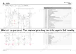
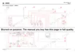
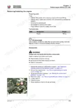
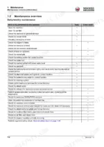
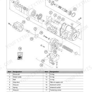
The Wacker Neuson WL28 service manual PDF pulls the wheel loader apart system by system: 300 pages under OEM ID 1000369264, running from the Perkins 404D-22 down to the quickhitch lock pin. Hydraulic diagrams map both the HDM19/3 and HDM19/4 loader unit circuits, with hose routing for the lift and tilt rams, while the electrical section pairs each circuit diagram with a component list and cable color key. When the machine won't creep forward, the travel drive troubleshooting tables walk you from symptom to a checked pressure cutoff and inching adjustment. Size a replacement battery at 77 Ah before you condemn the starter, and pull the wheel nuts to 150 Nm on their M14 x 1.5 studs. Every hour on stands is material somebody else moves. Bookmarked, text searchable, and light enough to travel, this PDF rides wherever the WL28 is parked.
What's Inside This Wacker Neuson WL28 Manual
| System | Pages | Key Topics |
|---|
| Introduction | 9-44 | Notice on This Service Manual (Use of the Service Manual, Explanation of Symbols and Abbreviations, Repair Instructions) |
| Operation | 45-51 | Overview of Control Elements (Control and Display Elements, Indicating Instruments, Loader Unit Control Lever, Overview of Switch Panels), Indicator Lights and Warning Lights |
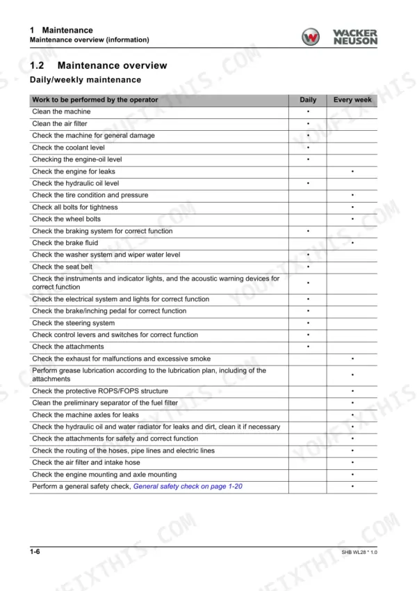
| Maintenance | 52-118 | Information on Maintenance (Responsibilities and Prerequisites, Safety Instructions, Battery Master Switch) |
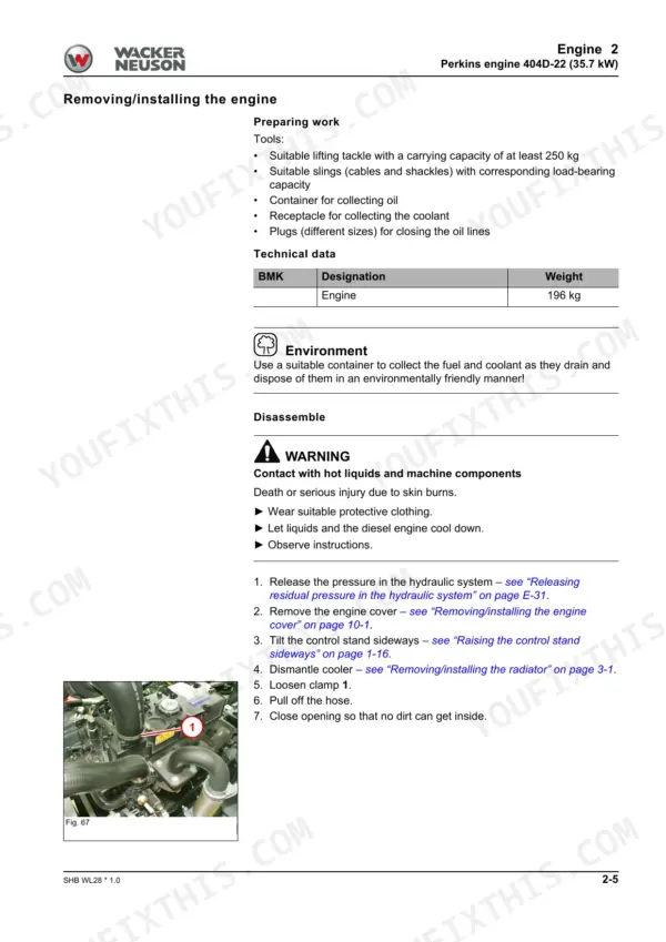
| Engine | 119-128 | Perkins Engine 404D-22 (Overview), Alternator (Removing the Alternator V-Belt, Removing the Alternator), Starter |
| Cooling | 129-132 | Radiator, Fan Blades |
| Travel Drive | 133-160 | Traveling Drive Hose Routing |
| Axles | 161-170 | Front Axle (Overview), Rear Axle (Overview), Type Label – Front/Rear Axle |
| Brake | 171-178 | Brake System Overview, Brake Pedal, Parking Brake, Parking Brake Bowden Cable, Master Brake Cylinder (Overview) |
| Steering System | 179-190 | Steering Orbitrol S4 (Overview), Steering Wheel, Steering Column, Steering Column Gas Strut, Steering Cylinder A21, Checking the Steering Hydraulics |
| Work Hydraulics | 191-228 | Overview, Hose Routing Lift and Tilt Rams, Gear Pump P37 (Overview, Checking the Gear Pump), Lock Cylinder A4, Lock Pin, Tilt Cylinder, Loader Unit, Lift Cylinder |
| Electrical System | 229-260 | Overview, Fuses (Boxes, Assignment), Joystick (Overview), Battery Master Switch, Electrical Diagram – Power Supply Engine, Electrical Diagram – Instrument |
| Trim | 261-264 | Engine Cover, Base Plate / Base Weight, Installing / Removing Rear Weight |
| Cab | 265-300 | Operator Seat, Indicating Instrument, Starter, 12 V Connector, Control Lever Console |
Quick Reference Specifications
| Specification | Value | Page |
|---|
| Battery | 77 Ah | p. 13 |
| General tightening torque M4 (8.8) | 3 Nm | p. 20 |
| Wheel nut tightening torque (M14 x 1.5) | 150 Nm | p. 20 |
| Hydraulic screw connections DIN 3865 (6mm lightweight series) | 10 Nm | p. 23 |
| Hydraulic screw connections DIN 3861 (6mm lightweight series) | 15 Nm | p. 24 |
| Hydraulic screw struts SDS Shape B/E (M10 x 1 lightweight series) | 18 Nm | p. 25 |
| Hydraulic screw struts Form F (M5) | 2.8 Nm | p. 26 |
| Main fuses | 40 A | p. 103 |
| Rated voltage | 12 V | p. 104 |
| F 1 Turn indicator, hazard warning system | 15 A | p. 230 |
| Engine Output | 35.7 kW | p. 13 |
| Battery Capacity | 77 Ah | p. 13 |