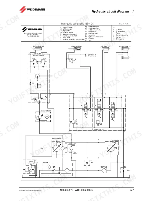
When the hydrostatic drive on a Weidemann 1250 CX35 wheel loader starts hunting, the fix runs through the variable displacement pump, and that is exactly where this 368-page Weidemann 1250 CX35 repair manual PDF (OEM ID 1000240975) earns its keep, before widening out to engine, axles, brakes, frame, cab and electrics. Full hydraulic and electrical circuit diagrams sit at the back, with plug and contact assignments so you can trace a dead sensor wire to its exact pin. Pressure test procedures walk you through checking the drive pump with a gauge against a target reading. Set valve play at 0.2 mm, torque wheel nuts to 285 Nm, refill the cooling system with roughly 7.5 liters. Invent a pressure setting and you can cook that pump. This bookmarked, text-searchable PDF puts the right procedure two clicks from the cover.
What's Inside This Weidemann 1250 CX35 Repair Manual
| System | Pages | Key Topics |
|---|---|---|
| Safety | 17-38 | |
| Technical Data, Testing Equipment and Special Tools | 39-72 | Technical Data, Filling Quantities, Tightening Torques, Pressure Values, Flow Rates, Safety Stickers, Testing Equipment (Test Pressure Gauge, Flow Meter, Test Pump) |
| Inspections, Maintenance Work and Troubleshooting | 73-122 | Complete Vehicle (Inspection Log) |
| Complete Vehicle | 123-132 | Helpful Tips, Protective Stickers |
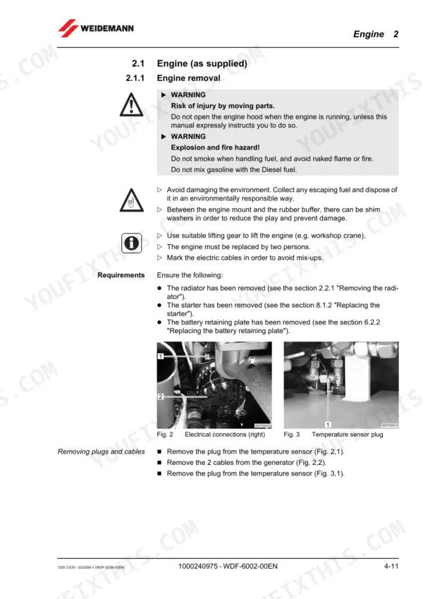
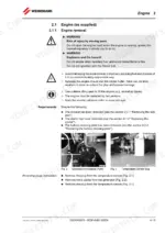
| Engine | 133-160 | Engine Removal, Engine Installation, Radiator, Air Filter System, Fuel System, Exhaust System |
| Hydraulic System | 161-204 | Depressurizing, Hydraulic Cylinder, Driving Hydraulics, Steering Hydraulics, Brake Hydraulics, Working Hydraulics, Auxiliary Hydraulics |
| Drive and Axles | 205-216 | Drive Shaft, Front Axle, Rear Axle, Twin Tires |
| Brake System (Mechanical Section) | 217-222 | Service Brake, Parking Brake |
| Vehicle Frame and Load Arm | 223-254 | Front Carriage, Rear Carriage, Center Joint, Step Plate, Load Arm, Tool Attachment |
| Operator's Platform and Cab | 255-278 | Driver's Seat, ROPS Bar, Cab, Windshield Wiper, Steering Column |
| Electrical System | 279-302 | Generator, Battery, Switches, Sensors, Relays, Lighting System |
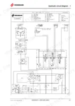
| Circuit Diagrams and Technical Descriptions | 311-352 | Hydraulic Circuit Diagram, Electrical Circuit Diagram |
| Supplier Service Manuals | 353-368 | Engine Workshop Manual, Variable Displ. Pump Repair Instructions, Variable Displ. Motor Repair Instructions, Repair Manual, Axle |
Quick Reference Specifications
| Specification | Value | Page |
|---|---|---|
| Wheel nut | 285 Nm | p. 49 |
| Hooked bolt nut (twin tires) | 285 Nm | p. 49 |
| Valve play (inlet and outlet) | 0.2 mm | p. 81 |
| Coolant quantity | approx. 7.5 l | p. 146 |
| Filter housing tightening | 1/6 of a rotation | p. 203 |
| Engine Output | 24.6 kW | p. 45 |
| Engine Capacity | 1,508 cm3 | p. 45 |
| Fuel Tank Capacity | 45 l | p. 47 |
| Engine Oil Capacity | 4.5 l | p. 47 |
| Cooling System Capacity | 7.5 l | p. 47 |
| Hydraulic Fluid Tank Capacity | 27 l | p. 47 |
| Front Axle Oil Capacity | 2.5 l | p. 47 |